 United States of America (1946)
Heavy Tank – None Built
The Chrysler K was an American heavy tank prototype designed in response to the increasing interest in heavy tanks at the end of the Second World War. The growth in interest was thanks, in no small part, to the discovery of German plans for super heavy tanks such as the Maus and E100. Most importantly, however, it was the appearance of the Soviet IS-3 at the Berlin victory parade in 1945 that really jump-started the process.
The appearance of the IS-3 sent a chill down the spine of all major allied powers. Each nation invested large amounts of time, energy, and resources in heavily armored tanks with powerful main armaments, not least the USA, whose only heavy tank was the M26 Pershing. This vehicle was considered to lack the required firepower and protection to face tanks such as the new IS-3.
One of these early designs was a submission from the Chrysler Motor Corporation. Called the ‘Chrysler K’, it would be armed with a 105 mm main gun, and armor up to 18 cm (7 inches) thick.

Background, the Stilwell Board
On 1st November 1945, the ‘Stilwell’ Board was convened, named after the man heading the meeting, General Joseph W. Stilwell. The official designation, however, was ‘War Department Equipment Review Board’. The findings of this board, submitted in a report on 19th January 1946, agreed, for the most part, with earlier recommendations that Light, Medium, and Heavy tanks should all be developed. However, experiments with Super Heavy tanks, such as the T28/T95, would be abandoned. Another omission from the report was the development of dedicated tank destroyers, following the Armored School’s (based at Fort Benning, Georgia) opinion that the best anti-tank weapon would be another tank. As such, a Heavy tank was favored in tank versus tank combat due to powerful guns and thick armor.
Chrysler’s Submission
The famous motor car company, Chrysler, based in Michigan, submitted their design for an unconventional Heavy tank to the Armored School in a presentation by a Mr. F. W. Slack at Fort Knox on 14th May 1946. It would be known as the ‘Chrysler K’. The origin of the ‘K’ may lie with Kaufman Thuma Keller, the president of the Chrysler Corporation from 1935 to 1950, and advocate of the creation of Detroit Arsenal (DA). It is quite possible that the tank was named after him, given his position at Chrysler, and his relationship with the military thanks to DA.

Design
Chrysler’s design would incorporate a number of features that were sophisticated for the period they were designed in. These included an electric motor, remote controlled secondary armaments, and a ‘Driver in Turret’ arrangement.
Armament
The 105 mm Tank Gun T5E1 was chosen as the main armament for Chrysler’s heavy tank. Designed in 1945, it was the popular choice for American Heavy tanks at the time and was also mounted on vehicles such as the Heavy Tank T29, and the Super Heavy Tank T28. The T5E1 had a medium velocity of 945 m/s (3,100 ft/s). A variety of ammunition (which was two-part, separately loading. eg, projectile loaded then charge) allowed it to be as good a bunker buster as a tank killer, with the gun proving capable of penetrating concrete as well as metal. Ammunition types included APBC-T (Armor-Piercing Ballistic-Capped – Tracer), HVAP-T (High-Velocity Armor-Piercing – Tracer), (Armor-Piercing Composite Rigid – Tracer) APCR-T and HE (High Explosive). The APBC-T shell could penetrate 135 mm (5.3 in) of armor at a 30-degree slope or 84 mm (3.3 in) of armor at a 60-degree slope, 914m (1,000yd).
At 7.53 m (24 ft 8 in), the barrel of the weapon was rather long. It was concluded that if the turret was mounted in the usual place, ie, centrally, the gun would become hazardous in convoy travel or whilst maneuvering. As such, the decision was made to place the turret at the back of the tank, off-setting the length of the gun. This design choice resulted in the vehicle having an overall length of 8.72 m (28 ft 7.5 in). This is just 7.62 cm (3 in) longer than the M26, despite the 105 mm gun being 16.5cm (6½ inches) longer than the 90 mm gun of the M26. The gun could elevate up to 25 degrees, and depress to 4-degrees.
Secondary armament was machine gun heavy, with three .50 Caliber (12.7mm) heavy machine guns and two .30 Caliber (7.62 mm) machine guns. One of the .50 Cal. machine guns was mounted coaxially with the main gun, the other two were placed in secondary turrets on the left and right rear corners of the hull. They had a limited horizontal traverse, but could be elevated upwards to defend against air attack (quite how practical this was is debatable). The two .30 Cal. machine guns were placed in blisters at the left and right top corners of the upper glacis. It is unknown whether they were ball mounted and had a degree of traverse, or whether they were completely fixed. All of these weapons were controlled and fired via a remote control system that was an improved and simplified version of the turret control system on the B-29 Superfortress bomber. If they were fixed, it is debatable as to whether these weapons would’ve been any use at all. Fixed, forward mounted machine guns like these were abandoned from designs long before the ‘K’. As an example, the original versions of the Medium Tank M3 and M4 Sherman had fixed forward facing MGs, but not the later ones. The layout of Machine guns on the hull is similar to an Army Ground Forces (AGF) design for a medium tank.
Turret
One problem with the T5E1 gun was that it had a long breech. Still, the turret had to accommodate this, 100 rounds of 105 mm ammunition, and the crew which consisted of a commander, gunner, loader, and the driver. As a result of this, the turret diameter had to be wider than anything previously designed for an American tank. The internal diameter was 2.9 meters (9 foot 10 inches), while the turret ring was 2.1 meters (86 inches), as opposed to 1.75 meters (69 inches), the largest of previous designs. It stated that 100 rounds of the separately loading 105mm ammunition were carried by the tank and that they were stored circumferentially around the turret. However, an investigation into this reveals that there simply isn’t enough room for all 100 rounds inside. Though it isn’t stated in any source material, it is reasonable to suggest that ammunition was stored under the turret, as there is enough unaccounted for space from the bottom of the hull to the floor of the turret. As stated this is speculation but it is not unreasonable as it was a very common practice.
The turret was hemispherical in shape, and cast in construction – this shape offered excellent ballistic protection. The turret face was 18 cm (7 inches) thick, while the rest of the casting was 7.62 cm (3 inches) thick. Ammunition was stored circumferentially at the rear of the turret. The face of the turret was reinforced with a mantlet consisting of a large, thick disc. The exact diameter and thickness of this mantlet plate are unknown.
An unusual feature of the Chrysler, for the time, was the fact that the driver was located in the turret with the rest of the crew. It wasn’t the first time that a tank could be driven from the turret, however, as a remote control box in the turret of the T23 allowed control from within should the driver be knocked out. It was believed that having all the crew in the turret provided better communication and cooperation. The turret still had the ability to rotate 360-degrees. The driver’s seat (and presumably controls) were geared so that they were always linear (always facing forward in relation to the hull) to the tanks hull, no matter where the turret was pointing. His position was surrounded by pericopes so no matter where he was in relation to the turret, he would always be able to see where he was going.
The exact crew positions in the turret are unknown, but looking at the position of hatches and pericopes we can make an educated assumption. It would appear the Driver sat at the front left of the turret with the Loader behind him. The gunner sat at the front right, with the Commander at his rear.

Propulsion
With the turret moved to the rear of the tank, the engine would now take up the space left at the front end. The power requirements for the vehicle were based on a US Ordnance Department idea calling for 20 hp per-ton for this projected 60-ton tank. The gasoline-fueled engine was an unspecified design by Chrysler and was powerful with a projected output of 1,200 hp.
The engine was placed in the front end of the hull was to was to be connected to two electric motors that formed the tank’s final drives at the front of the vehicle. This system is similar to that used on the Medium Tank T23 prototype. The electric drive system on the ‘K’ tank was designed by a Mr. Rodger.
The engine system was fed by 600-US gallon (2727 liter) fuel tanks. The exact number of tanks is unknown, but it is likely to be at least two, judging by other American heavy tanks of the time.
Suspension
The suspension was the usual torsion bar type. There were eight twin road-wheels per side, with the idler at the back and the drive sprocket at the front. The idler was the same type of wheel used for the road wheels. The return of the track was not supported by rollers. This is known as a flat track suspension and is common on Soviet tanks such as the T-54 and so on. The track was 76.2 cm (30 inches) wide.
Hull
The hull was rather square in its overall shape, with the frontal plate 18 cm (7 inches) thick and angled at 30-degrees. Such angling brought the effective thickness up to roughly 36 cm (14 inches). Armor on the tank’s sponsons was less impressive being just 7.62 cm (3 inches) thick. They were sloped inwards slightly at around 20-degrees, this would’ve made the effective thickness 8.1 cm (3.1 inches). A 25 mm (1 inch) thick armored floor protected the underside of the vehicle. The tank was 3.9 meters (12 foot 8 inches) wide. For rail travel, the sponsons and outer halves of the road-wheels could be removed.
The overall height of the ‘K’ tank, turret included, was 2.6 meters (8 foot 8 inches) tall. This was 7.62 cm (3 inches) shorter than the M26. Altogether, the tank was projected to weigh 60 tons.

Fate
Funds for tank design gradually dwindled after the Second World War. As such, the Chrysler K tank never left the development stage, with only line drawings and a scale model produced. Unfortunately, the drawings and scale model are not thought to survive, and only a photo of the model remains. The project was abandoned, with attention turning to more conventional tank designs such as the Heavy Tank T43, which would eventually become America’s last heavy tank, the 120 mm Gun Tank M103.
Some of the design features of the ‘K’ tank were carried over into future tank projects. The ‘Driver in Turret’ concept was utilized on the M48 Patton based M50/53 self-propelled gun, and also the MBT-70 and subsequent prototypes. To the east, the Soviets also used this concept in their prototype medium tank, the Object 416.
The Other ‘K’
This heavy tank was not the only tank designed by Chrysler to bare the ‘K’ designation. Twenty-two years later, in 1968, Chrysler would put forward another design intended to be a possible upgrade of the 105mm Gun Tank M60. The design featured a brand new, comparatively smaller turret and a new main gun.
Two guns were tested on the tank. One of these was the 152 mm Gun Launcher XM150, a modified version of the gun used in the MBT-70 project. The gun could fire conventional Kinetic Energy (KE) rounds, or launch Anti-Tank Guided MIssiles (ATGMs). The other gun was the 120 mm Delta Gun. This was a Hyper-Velocity Gun that was smooth-bore and fired an Armor-Piercing Fin-Stabilised Discarding-Sabot (APFSDS) round. The gun also used combustible cartridge cases, meaning the entirety of the round would ignite upon firing, much liked the bagged charges used on the 120 mm gun of the British Chieftain.
Another modification that Chrysler designed for the M60 was for the suspension, specifically the torsion bars. A modification by Chrysler allowed the wheels to have an extra 45 percent travel when actuating on their suspension arms.
Despite notable merits to the Chrysler’s ‘K’ tank, the design was not accepted into service. Two mockup turrets were constructed and tested on M60 hulls, but at the time, all spare funds were being spent on equipment for the lingering Vietnam War. As such, all work on the vehicle was dropped.

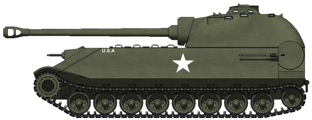
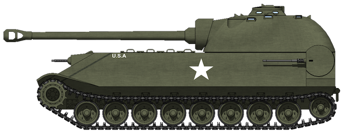
Profile of the Chrysler ‘K’ Heavy Tank with a speculative livery of Olive Drab with basic US Markings. Both the color and markings were commonplace at the time. Length and height wise, the ‘K’ wouldn’t have been much larger than the United States then serving tank, the M26 Pershing. At the time, the M26 was considered a Heavy Tank.
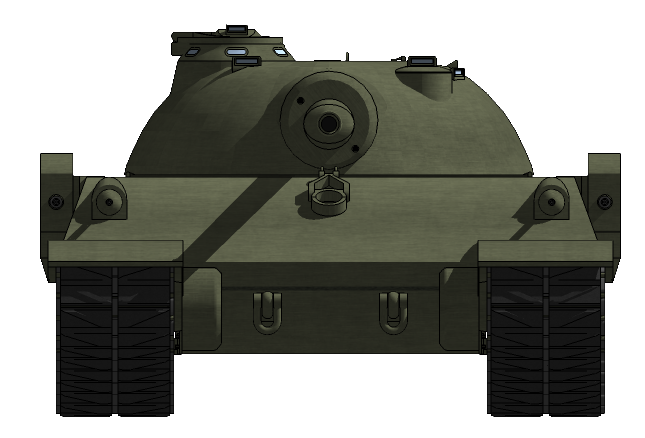
A head-on view of the ‘K’ Heavy Tank. This view shows just how wide tank would’ve been. While the ‘K’ was only a maximum of 7.62 cm (3 in) taller and longer than the M26, it was much wider at 3.9 m (12ft 8in), approximately 40cm (16in) wider than the M26. Note also, the 76.2 cm (30 in) wide tracks, and how far the remote rear turrets extend from the hull sides.
Both of these Illustrations were modeled by Mr. C. Ryan and were funded by our Patreon Campaign.
Specifications |
|
| Dimensions (L-w-H) | 8.72 x 3.9 x 2.6 Meters (28 ft 7.5 in x 12ft 8in x 8ft 8in) |
| Total weight, battle ready | 60 tons |
| Armor | Bow: 18cm (7in), angled at 30-degrees (36cm, 14in, effective) Sides: 7.62cm (3in), angled 20-degrees (8.1cm, 3.1in, effective) Turret Face: 18cm (7in) Turret Sides/Top/Rear: 7.62cm (3in) |
| Crew | 4 (Commander, Driver, Loaders, Gunner) |
| Propulsion | 1,200 hp Chrysler Petrol/Electric engine |
| Suspensions | Torsion bars |
| Armament | Main: 105mm Gun T5E1 Sec: 2 x Browning M2HB 50. cal (12.7mm) MGs in remote turrets, 3 x cal.30 (7.62 mm) Browning MGs. 2 x in fixed mounts on the bow, 1 x coaxial. |
Sources
Presentation by Mr. F. W. Slack, 14th May 1946. Original document provided by The Richard Hunnicutt Collection in the at the National Armor and Cavalry Museum Archives. Thanks for this are also extended to the Museum’s Curator, Rob Cogan.
Presidio Press, Firepower: A History of the American Heavy Tank, R. P. Hunicutt
Presidio Press, Patton: A History of the American Main Battle Tank, Vol. 1, R. P. Hunicutt
18 replies on “Chrysler K (1946)”
Really thought this tank was a fabrication on wot but i guess i was wrong. But hard to know what is real and what is fake after the amount of fake tanks added XD
aparently this is an OP tank in WoT but i havent come across it yet
It was a real design but the version represented in the game has had some liberties taken in regards to the thickness of the armour and the capabilities of the main gun
TE Moderator
So the .30 cal. guns were 100% fixed? From the images it looks like it could be a ball mount similar to that of the Sherman.
I have updated the article. I don’t really know whether they were fixed or not, its an area of detail we don’t have I’m afraid.
– Author
No worries, thanks for the clarification though.
It very much resembles a ball mount but after modelling it, I’m not sure there would be much space at all for any useful amount of movement, especially if the mounts were armoured, had space inside reserved for the ammo belt AND the mechanism for moving them remotely.
Chrysler must really love the letter K. There’s also the Chrysler K Car from the 1980s … LOL
May I translate this article into Chinese?
Yes. Just mention us as the source of the original article and link us.
Thank you very much.
Oh god this thing. This was it. This was the tank that caused me to quit World Of Tanks forever.
everyone plays wot here right?
Nope, most of us don’t.
yea i find it terribly unrealistic and pay-to-win dominated.
are you sure about armor thickness? it has no sens. Hull is almost unpenetratable for kinetic projectiles, but non sloped turret face is paper for HVAP/APCR.
Would be very scary to face in battle…
Love playing this one in WoT so much, and always liked the look of it. I still cackle every time that wonderful side armour bounces a kill shot from an ISU