 United States of America (1942)
Amphibious Armored Vehicle – None Built
Nothing spurs invention like war they say, and this is very true for Allison Williams. On the 30th December 1942, Allison Williams, from Yazoo City, Mississippi, filed a patent for a design of one of the most unusual armored cars of World War Two.
The design was created with the intention of providing “amphibian vehicles of high maneuverability adapted to attack and destroy a military tank and provided with a plurality of independent self-contained power units for driving the same”
There are three elements therefore to the design. The amphibian nature of the vehicle, the anti-tank nature of the design and, finally, the drive system.
 Colonel Allison Ridley Williams (1891-1966). Photo: Nashvillekit via findagrave.com
The Designer
Colonel Allison Ridley Williams (1891-1966) was born in Benton, Mississippi on 10th August 1891. He did not limit himself to just this amphibian vehicle design. He was already known as an inventor specializing in electrical control systems in the 1930s with patents filed for various steering and braking system and was referenced in Popular Science Magazine in 1939 for an electrical device controlling braking when turning. During the war, he designed not only this vehicle, but also two more successful designs for mine clearance equipment in 1944. Post-war, he continued his electrical work with patents on electric brake control for vehicles and aircraft until 1960. He is referenced in most patents as living in Yazoo from 1930s until the late 1940s after which he moved to Vicksburg, Mississippi, where he died on 27th August 1966, aged 75.
Nature and Design
The first two elements of this design are connected. Williams was clear that whilst military tanks were well designed using caterpillar tracks, too much reliance had been placed on defeating them with tanks. As those tanks have roughly the same limitations imposed on them by using caterpillar tracks and extreme weight, the solution was to go light and to go mobile. As most tanks are unable to operate in water, an agile vehicle able to operate both on- and off-road and also just as capably in water would allow it to flank enemy tanks. Add in an anti-tank gun on such a platform and suddenly you have an extremely capable tank destroyer which can go where tanks cannot.

Rear view of the amphibian vehicle providing a good view of the tyre tread and overall height of the vehicle. Source: US Patent US2432107
Given that the design was drawn up in 1942, after the USA had started fighting the Japanese in the Far East, the abundance of soft, marshy or marginal ground etc. would have made the deployment of such a machine very desirable. An obvious additional advantage is that the vehicle would not be reliant on landing craft or bridging equipment to cross rivers or lakes.
Armor
No specific armor is specified, but Williams is clear that the crew must be protected from enemy gunfire and that the drive mechanisms, in particular, should be well armored. With the body armored it makes sense to armor the wheels too, as this has the advantage of lowering the center of gravity for the design, an important consideration when floating or traversing rough country. Steel was the material of choice for the machine, specifically ‘heavy steel shells’ for the wheels, which, with the combination of the angled surface and thickness, ensured that no bullets or small caliber shot were going to incapacitate the vehicle. Puncturing of the wheels would be especially hazardous if the vehicle was floating, although the air pressure inside the wheel cavity was to be maintained at a pressure higher than the atmospheric pressure outside to resist the entry of any water. As the vehicle would float at half the height of the tires, a large amount of the vehicle would still be exposed to fire when crossing water.
Armament
Although the caliber of the main armament is not given, Williams is clear that a single anti-tank gun should be carried and although he doesn’t specify which sort of standard anti-tank gun in military service was likely envisaged. Additionally, a plurality of other armaments could also be carried in addition to, or instead of, this anti-tank gun. This armament is carried within a large fully rotating turret atop the main body of the vehicle, with rotation driven from below via a system of gearing. The turret provides for an elevation range on the main gun of -10 to +15 degrees. The turret itself is very tall, more than half of the height of the overall vehicle, and connects to the very low flat hull. As such, the hull provides a very small target from both front and side. Inside the turret, the main gun is mounted not on trunnions, as in a conventional turret, but on a turret floor mounted pintle allowing for completely independent slewing of the gun, which is partly independent of turret rotation. In this manner, the gun could be moved 30 degrees (15 degrees left and right). A smaller gun coaxial to the main gun is also drawn and presumably was a machine-gun.

Top-down view of the Amphibian vehicle showing the ability of the anti-tank gun to slew independent of the turret. Source: US Patent US2432107
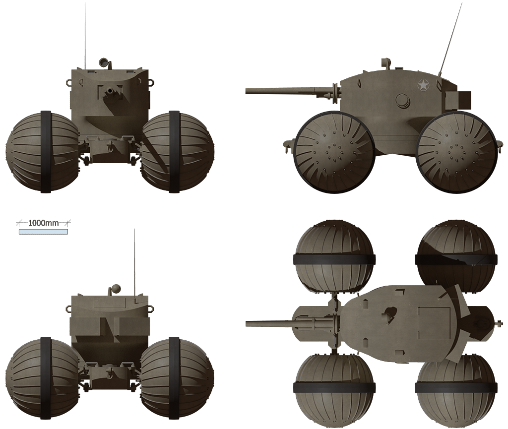
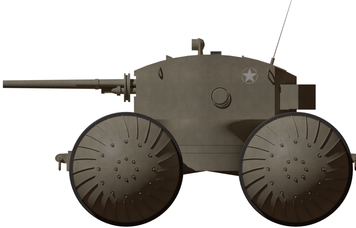
A four-view illustration of Williams’ Amphibious Vehicle produced by ‘Giganaut’, funded by our Patreon Campaign.
Crew
The crew selected was to consist of four men. A commander, a driver, gunner, and the fourth member who was to act as a lookout or replacement gunner or driver. Presumably, if the machine to see action, he would simply have been a loader for the main gun. All of these crewmen were to be enclosed within the turret as there is no space within the hull for them and no indication of any access hatches for them in the hull. All access to the vehicle is provided for by means of a single large hatch on the top of the turret. Historically, crew-in-turret designs have failed due to the inability to move the turret whilst driving as it disorientates the driver, but, as the gun can slew independent of the turret, the design at least permits some offensive action to be taken without any turret movement distracting the driver.

Spherical wheel with drive unit contained inside. Source: Patent US2432107.
Power
Unlike a conventional armored car, the William Amphibian Vehicle had not just one engine and a transmission, but no less than four completely separate and independent power units protected by “good armor” within a watertight spherical wheel. Each power unit was enclosed within the completely spherical wheels covered, as in the patent drawing, with a tread pattern for both grip off-road, and for drive in water. Each wheel was mounted on a pivoting bracket permitting the wheel to move horizontally but not vertically. A hydraulic coupling moved through this pivot connection running to the engine for the machine. Therefore, a single engine located in the body of the wheel drove it with the speed of the motor determined via a hydraulic linkage permitting both flexibility and protection from shock. Whilst this system was very complex it had significant advantages for the design providing a lower center of gravity, reducing hull size and weight and improving the balance in the water.
Driving and steering were done by means of a joystick controlling the delivery of pressurized fluid via the couplings to each drive. More pressure to the left drove the left-hand wheels harder than the right causing a right turn and vice versa. Thus, steering of the vehicle was remarkably simple, especially compared to the steering levers common to tanks of the era. Acceleration, therefore, would be by means of uniform forwards pressure on the stick and slowing down by the stick being pulled back. Presumably, this stick would be spring controlled so that its natural position was in the ‘back’ position with no pressure applied to any motor. Should any one motor fail, the vehicle could still maneuver, and as long as at least one motor was still functional on each side, the only effect of losing the other two power units would be reduced performance. Engine exhaust did not, as might be expected, vent out through the outside of the wheel, but actually backward through the inside of the coupling through a one-way valve. Air for the engine was supplied through the same linkage as the hydraulic coupling and links back through the crew compartment to the roof. Each motor sucked in external cool air through the crew area providing relief from heat and fumes for the crew.
Manufacture
Each wheel was to be made from two hemispherical shells bolted together around a central rubber tired wheel acting as a normal wheel when on a paved road. As the ground got softer then progressively more of the wheel would be in contact with the ground. In this way, the wheels actually gained significantly more traction even when sinking very slightly and even when the ground became unable to bear the weight of the vehicle would actually be buoyant.
Conclusion
The Williams Amphibious Vehicle is an unusual vehicle in many regards. The selection of having all the crew in the turret is not unique but it also is not common either. The drive system is probably the most unusual part of the design and although hub-motors have been around a long time offering lots of potential benefits the military, in general, prefer simpler and cheaper conventional drive systems. Whilst the Williams Amphibious Vehicle looks odd with its ball-shaped wheels and tiny body the design is undoubtedly sound, at least on paper. In many ways given the nature of fighting the US had to do between 1943 and 1945 a vehicle with the sort of mobility Williams envisaged could have proven to be very useful but as it was the design was not developed. Perhaps an opportunity missed.
Source
US Patent US2432107 filed 30th December 1942, granted 9th December 1947
Popular Science Magazine July 1939
Yazoo Herald, Mississippi 20th April 1961
Findagrave.com
3 replies on “Williams’ Amphibious Vehicle”
Looks like something straight out of a Star Wars.
one of the more sensible crazy projects I have seen, a nice design
the crew section is kinda weird in the way it is grammatically.