 United Kingdom (1915)
Prototype – 1 Built
The First World War was supposed to end quickly. Most of the high-ranking officials of the participating countries expected and planned for a short war, in which they would quickly crush their enemies and win glory and territories for their nations. However, after the German defeat at the First Battle of the Marne (6-12th September 1914), the Germans started digging in behind the River Aisne. The war was just one month old.
By March 1915, the trench lines on the Western Front spanned from the English Channel to the Swiss frontier. Bogged down in soft mud caused by heavy artillery bombing and rain, ensnared in barbed wire, entangled in numerous successive defensive lines, and decimated by machine-gun fire, offensives on the Western Front yielded little results and appalling casualties. The British and the French started looking for a solution to this ‘deadly equation’. The end result on the British end would be the first tank deployment in the world, preceded by the first tank prototype ever built, the ‘Lincoln No.1 Machine’.

The Lincoln No.1 Machine on trials. The tarpaulins concealing the vehicle have the name of the firm William Foster and Co. of Lincoln on them. Photo: SOURCE
A Historiographical Note
In October 1919, a Royal Commission on Awards to Inventors investigated about a dozen claims with regards to the invention of the tank. The claimants included personalities such as Winston Churchill, R.E.B.Crompton, William Tritton, Eustace d’Eyncourt and other important persons in the development of the tank. A large prize was awarded to those that the Commission deemed to be the ‘inventors’, although such a complicated machine could not be ‘invented’ by only two men and was a concentrated effort. However, the works of this Commission have driven a large number of divergent claims with regards to the development of the tank, and thus of the Lincoln No.1 Machine as well.
Furthermore, the Lincoln No.1 Machine (even under its more famous Little Willie name), while eliciting a large deal of interest, especially due to the centennial of the First World War, has only been treated superficially in the specialised literature, being glossed over in favor of the iconic rhomboid tanks.
A Flurry of Ideas
The tank, as it crashed through the German lines in 1916, did not appear out of a vacuum. Armored cars had been built and showcased around Europe for more than a decade, even though in small numbers and often facing vitriolic opposition. However, the armored car was incapable of traversing no man’s land. Various tank-like vehicles were also proposed around the continent and were just as rigorously ignored.
A myriad of solutions were soon envisaged, including portable bridges, pedrails, steam rollers and huge wheels. The tracked-vehicle did not immediately emerge as the redeeming solution. In fact, on 17th February 1915, a committee from the War Office (not to be confused with the later Landship Committee of the Admiralty) attended a demonstration of a Holt Tractor at Shoeburyness, some 40 miles west of London. However, the members of the committee were highly critical of the vehicle, especially regarding the weight and costs of an armored vehicle based on the Holt tractor. And thus the army turned its back on the tank idea.
The Navy Steps In
One of the major users of armored cars on the Western Front was, quite surprisingly, the Royal Navy Air Service, or RNAS. The First Lord of the Admiralty, Sir Winston Churchill, had already joined the landship discussion in January 1915, with a letter to the Prime Minister speaking about armored steam tractors that would crush barbed wire, cross trenches, and deliver infantry to the enemy lines. While other fanciful ideas and ludicrous designs were discussed, on the 22nd February 1915, the Admiralty’s Landship Committee met for the first time under the chairmanship of Eustace d’Eyncourt, deciding to further look into two options, tracked vehicles or vehicles with large wheels.
With no reliable tracks available in Great Britain at the time, an officer was sent to the USA to try and locate some. The mission resulted in the delivery of the Killen-Strait tractor followed by two Creeping Grip tractors and an elongated set of tracks from the Bullock company in Chicago. The Bullock tracks arrived in August 1915.

An excellent shot of the two of the two Bullock Creeping Grip tractors that were bought on behalf of the Landship Committee and linked together. This was a development parallel to what would become the Lincoln No.1 Machine. However, this photograph of the original suspension also demonstrates the sagging that the elongated version on the Lincoln No.1 Machine suffered from. Because the tank’s tracks were much longer, they were even more likely to not connect correctly on the far end of the trench and be thrown off. Photo: IWM
In June 1915, the Army finally expressed its interest in getting back into the project, but the development would remain in Admiralty hands for a while longer. On 22nd (other sources state 24th) of July, the Lincoln-based William Foster & Company was finally contracted to build a prototype landship based on the longer version of the Bullock tracks. This choice came due to their previous experience with building tracked vehicles and their involvement with the military, having developed the humongous Daimler Foster artillery tractors and also having been involved in developing their own trench-crossing vehicle.
The vehicle at this stage is also described as based on one half of the articulated Crompton machine, as in an order from the Landship Committee from the 30th of July. This did not mean it actually was one half of the Crompton machine, but just that it used the same tracks.
However, from this short incubation period in the Navy’s berth, a number of components of the tank have received ship-like designations that are in use to this day. Tanks have hulls (from the watertight shell of a ship), hatches for the crew members, sometimes have weapon ports and sponsons (a part of a ship that projects beyond the side of the hull), one or more turrets (an entirely enclosed part of a ship that could rotate with the armament mounted in it), the hull machine-gun is often called a bow MG (the bow is the front of a ship) and the part above the engine is the engine deck (the floors on a ship).
The Lincoln No. 1 Machine
The paternity of the design that emerged is contested, with both R.E.B.Crompton and William Tritton claiming it. The former had led the design efforts of the Landship Committee before his contract ending prior to the end of the construction of the prototype and he was replaced with Tritton. What is known is that Tritton at least knew of a set of detailed drawings done by Crompton and an assistant, Mr. Rigby. Tritton contests having received a full set of detailed drawings, with other sources claiming he did, in fact, receive them. Regardless, construction finally began on 11th August. On the 9th (or 8th) of September, just four weeks later, it was already being driven around the yard at the Foster Company’s testing grounds.

The Lincoln No.1 Machine during trials. Notice the turret visible under the canvas and what looks like a gun holding up the cover. The vehicle was going over a small hill. The steering wheels are visible at the rear, as is the ‘nose’ that protrudes in front of the tracks. Note that the image was improperly scanned. Source: IWM Q 14543
The Name
The vehicle presented in this article, featuring the Bullock tracks, the simple version of the rear wheels and the large turret, was known as either the ‘Lincoln No.1 Machine’, after the locality it was built in, or the ‘Tritton’, after its head designer, at the time of its construction and testing. Some sources also state that William Tritton called both this design and Mother as ‘Juggernaut’.
The ‘Little Willie’ nickname seems to have only appeared after the Tritton tracks were fitted, sometime in January 1916, accompanying the ‘Big Willie’, better known as ‘Mother’ or ‘His Majesty’s Land Ship Centipede’. There is no proof that the vehicle ever officially ceased being called the ‘Lincoln No.1 Machine’, even after its upgrade.
It is thus the author’s choice to use the designations to differentiate between the ‘Lincoln No.1 Machine’ fitted with the Bullock tracks and the ‘Little Willie’ fitted with the Tritton tracks.
A note on the ‘tank’ designation should also be made. The persons involved in the project decided to adopt a cover name for the new vehicle being prepared, ‘landship’ being deemed as too conspicuous. ‘Water Carrier’ was first proposed, but the shorter version of ‘tank’ eventually won out and has remained in worldwide use. It is, however, unclear when the ‘tank’ designation first appeared and if it was applied to the Lincoln No.1 Machine. J.F.C. Fuller, in his book ‘Tanks in the Great War 1914-1918’ claims that it was first used on 24th December 1915 for a proposed ‘Tank Supply Committee’ that would take over armored development in the United Kingdom. This Committee was indeed formed in September 1916 upon the dissolution of the Landships Committee.
Another explanation given for the tank name is that the ‘chassis’ and the ‘body’ of the vehicle were separated, with the ‘chassis’, actually the Creeping Grip track system, being described as a training vehicle for the Royal Marine Artillery and the hull of the tank as a water carrier for Mesopotamia. This could also explain the photograph of the Lincoln No.1 Machine hull in the Foster factory, showing an almost complete vehicle, but with no running gear and no holes cut into the hull.
Construction
The large, boxy vehicle was of riveted construction using an iron-angle frame, being made out of boiler plate and not bullet-proof armor. This was, in the end, meant to be a test prototype and not to see combat. An angular nose protruded from the front, inside which the steering controls were located. Just above the glacis of this ‘nose’ were two hatches, hinged on the upper part, which allowed the driver and co-driver to see forwards. Both these hatches also featured a small horizontal slit with a shutter that should have allowed some limited visibility under fire. A similar design would be kept for most British tanks used in World War One. These could be held open using a strut. It is unclear if the circular gun slot that later appeared between the two hatches on Little Willie was present on the Lincoln No.1 Machine as well or if it was a later modification.
Two large, almost full-length sponsons were present on the sides, emerging from just over the tracks and reaching up to the top of the vehicle. Each of them had three weapon ports with a rotating shutter when not in use. One large headlight could be mounted on either side. The rear of the tank hosted the coupling that held the rear pair of wheels. This coupling allowed the wheels to be turned from the inside through a small hole at the rear of the tank. The rear assembly was fixed to mounting points on each side at the rear and connected to a large spring in the lower part of the rear. A door was also present on the left side of the tank, with a pistol port at its top. This seems to have been the only way of accessing the tank. A radiator fill port was present on the upper right side.

A photo showing the rear of the Lincoln No.1 Machine. The rear wheels and their mechanism are visible, as is the cable used to control them. The large door on the left is open, probably in order to aid ventilation inside. The small tubular piece of metal protruding out of the oval port hole in the center of the right-hand door at the back of the vehicle is the radiator filling tube. The constant use of a large canvas sheet over the vehicle was for security purposes, meant to disguise the machine. Photo: SOURCE
The rear wheels were meant to help the tank in steering and could be turned left and right, like on a regular car. They were based on the Ackerman steering geometry used in most wheeled vehicles. Because they were at the rear, when the wheels were turned to the left they would then turn the tank to the right, similar to how a car handles when driven in reverse. This was not the main means of steering, but was meant to augment the track steering and allow for more efficient shallow turns. The usual brake differential, which was the main mode of steering, led to the loss of a good deal of the tank’s power. Also, when crossing a trench, the wheels would offer extra support to the tank, allowing it to pass over trenches and not slide backward at the last moment.
The rear wheels on the Lincoln No.1 Machine were the same as the front wheels on the Foster-Daimler tractor, with a prominent circumferential central rib on the wheels. This feature would be kept for the Mark I tanks, but was removed afterward. The wheels where 1.37 m (4 ½ ft) in diameter. A large coil spring was also present, one end connected to the rear of the hull and the other to the rear wheel frame. This spring pulled the wheels downward, ensuring good contact with the terrain. The Lincoln No.1 Machine did not have the hydraulic system that could raise the rear wheels when needed.

The rear wheels on the Lincoln No.1 Machine. The attachment points and the large spring that held them in place are visible. Photo: SOURCE
The top of the tank had five structural support ribs running transversely, with another reinforcement running longitudinally on the centre. There was a radiator air intake at the rear right. A fan intake was placed further forward on the right, but behind the turret. Two more holes were present next to the fan. One of them was probably the fuel intake and the other the exhaust, although that is just speculation.
The Lincoln No.1 Machine also featured a large circular turret placed near the middle of the vehicle. There is some discussion around the placement of the turret, focusing on whether it was centered or offset to one side. Investigations on Little Willie, which survives in the Bovington Tank Museum, show that the circular plate that was used to cover the turret opening is off-center. However, it is unclear if this is because the turret opening itself is off-center or if only the plate was mounted to one side.
David Fletcher, in ‘The British Tank: 1915-1919’, states that the turret did not have any rotation mechanism installed for the prototype. It was not just a dummy weight though, as a photo taken during construction of the vehicle shows it being made of riveted steel, same as the rest of the tank. Contrary to various online opinions that state that the turret was meant to be fixed in place, it was almost assuredly designed to rotate on the final design. Turrets were not a new concept at the time, having already been used extensively on armored cars and on ships. Furthermore, the circular shape was too difficult to create and had no advantages over a rectangular shape if it was meant to be a fixed casemate.
Unfortunately, little else is known about the turret except for the fact it had at least one more weapon port. There is also a chalk lining on the front part, possibly showing where the cut-out for the gun would be made. There is a single photo showing the turret during the construction of the Lincoln No.1 Machine. The turret is well hidden by a textile cover in all the other photos of the vehicle. This was meant to obscure the role of the vehicle to any uninvited enquirers.

The only photo showing the Lincoln No.1 Machine’s turret. This was taken during construction at William Foster and Co. Note that the front hatches for the driver and co-driver have not been cut in yet. Neither have the side gun ports. The ‘tube’ sticking out of the lower side of the hull next to the ladder is the central pivoting axle, on which the track frames where mounted and also supported one drive chain sprocket. It is unclear what the thing attached to the side of the hull is, although it is possible it was used for cutting the weapon ports. Photo: SOURCE
The running gear was not directly connected to the hull of the vehicle. All the wheels that held the track were mounted on a frame that was then connected to a central pivoting axle on each side. Two other brackets on each side, one at the front and one at the rear, controlled the pitch of the body.
Armament
The Lincoln No.1 Machine was meant to sport impressive weaponry for the time. The turret was intended to mount a Quick Firing (QF) 2-pounder (40mm) Mark II gun. This watercooled Vickers-Maxim type autocannon was already in use in the Royal Navy as a ship-borne anti-aircraft gun. This weapon had a relatively high-rate of fire, being belt-fed, and a high muzzle velocity (585 m/s). However, the rather small shell had no explosive power, its main ammunition being solid shells, and would have struggled against enemy emplacements and machine-gun nests. This would lead to its abandonment by the nascent tank arm in favor of the 6-pounder.
Another machine-gun was meant to be mounted in the weapon port to the left of the gun. This was not coaxial and could be independently aimed.

A Quick-Firing 2-pounder (40mm) gun used as an Anti-Aircraft Gun on a train car in the Middle East, in Mesopotamia, in 1918. Photo: Q 24291, Imperial War Museum archives
Besides this, up to six Madsen light machine-guns were meant to be used. The hull of the Lincoln No.1 Machine had three pistol ports on each side and another one at the rear, from which the machine-guns were probably meant to be fired. They would be mounted on trunions and aimed through special sights using a short pistol grip. The barrel would have had a special cover. The machine-guns were magazine fed, with the magazine on the top part of the weapon. It can be speculated that the machine-guns could be dismounted for use outside the tank if needed.
The Madsens had been ordered from Denmark in 1914 for land and air use, but they were never shipped to Great Britain because the route was well covered by the German High Seas fleet and submarines. The Madsens were subsequently abandoned by the time the Tank Mark I rolled out at Flers-Courcelette, replaced by the locally-built Hotchkiss and Vickers machine-guns.

The tank version of the Madsen light machine-gun. Photo: The Madsen Machine Rifle. Main Characteristics, Organization and Tactical Use
Another source, ‘Lincoln No.1 Machine, Little Willie’ by M.J.Verrall, states that the machine-guns would be Lewis or Hotchkiss ones. The same source also states a Maxim machine-gun would have been fitted in the circular port at the front of the tank.
Some sources also state that some rifles would be carried, probably for use by the crew if they dismounted. Ammunition capacity and stowage are unknown. It is almost certain that the Lincoln No.1 Machine never got to the point where these were even considered.
Powerpack
The engine used in the Lincoln No.1 Machine was the same 105 hp Daimler-Foster already in use on Foster’s gigantic artillery tractors. This was a six-cylinder sleeve-valve petrol engine. The sleeve-valve system was an alternative to the currently usual poppet valve. These devices are used to control the flow of fuel into the piston.
At its invention, the sleeve-valve engine was significantly quieter and had markedly improved reliability, being a favorite for luxury machines. This came at the cost of excessive lubricating oil use. In the end, availability, Foster’s experience with the engine and the fact it was already in production and could be put into new tanks quickly led to its use in the Lincoln No.1 Machine.

A 1913 article from The Commercial Motor magazine showing a photo of the 105 hp Daimler engine that was later used in the Lincoln No.1 Machine. Photo: Commercial Motor April 1913
The engine was placed towards the rear of the tank, partially underneath the turret, which would have made the latter’s use more complicated. This peculiar arrangement was probably chosen in order to give a better weight distribution and allow better crew access to the engine.
Beside the engine, a gearbox (two forward speeds, one reverse), a worm differential, steering controls, and a radiator were also present. The radiator was placed at the rear-right of the vehicle and the differential was probably placed in the middle part of the vehicle. The steering controls were at the front, close to the two driver positions. One driver controlled the acceleration, gearbox and rear wheels, while the other one controlled the brakes for each track. Two fuel tanks were mounted in the rear upper sides of the hull.
The power transfer arrangement from the differential to the drive sprocket was ludicrously complicated. The drive shafts (one on each side) had a sprocket connected through a chain to another sprocket fitted to the central pivoting axle. This was connected to a second sprocket, also fitted to the central pivoting axle, which was connected by a second chain to a lantern pinion that drove the drive sprocket at the rear of the tank. A similarly complicated system was maintained on the subsequent Tank Mark I-IV. This had the advantage that the whole power transfer arrangement was more resistant to shocks, since the chains would not transmit exterior shocks to the gearbox and differential.

Illustration showing a cutaway of the complicated power transfer arrangement on the Tank Mark IV. Photo: Source unknown, taken from Pinterest

The slightly less complicated power transfer arrangement on the Tank Mark V, showing the two chain-connected sprockets, the second of which meshes with the drive sprocket. Photo: The Tank Corps, by Major Clough Williams-Ellis, M. C., and A. Williams-Ellis

A Daimler Foster artillery tractor. The size of this machine is immediately apparent. The engine and front wheels were reused on the Lincoln No.1 Machine. OHMS stands for On His Majesty’s Service. Photo: SOURCE
Crew
The number of crew members that the Little Willie would have accommodated is given as five in a single source, a speech given at an anniversary dinner 50 years later for the designers. It is unclear how accurate this information is. Two crew positions were present at the front of the vehicle, for the driver and the co-driver. At least two more crewmen would have been present in the turret, with the other one (or possibly more) manning the machine-guns in the sponsons.
The Track Units
The entire track system of the Lincoln No.1 Machine was imported from the United States, from the Bullock company of Chicago. They were an elongated version of the tracks used on the Creeping Grip tractor built by the same company. This was done because there were no suitable track producers in the United Kingdom and due to expedience, as they were already in production (even though thousands of miles and an ocean away).

The Bullock ‘Creeping Grip’ short tracks, as used on the original tractor. Photo: Commercial Motor magazine, 3rd April 1919
The drive sprocket was at the rear, while the idler was at the front. They both had a distinctive, slightly-spiraled design and were cast. The idler could be used to adjust the track tension. Eight equally-spaced small road wheels held the weight of the tank. These were all held on a single fixed frame. All photos of the Lincoln No.1 Machine show a significant curvature of the roadwheel line. This was apparently done in order to reduce the amount of track in contact with the ground and thus allow the tank to steer. There is indeed an inverse relationship between the contact length of the track and the ease of steering. The return of the track was supported by five return rollers, all fixed to another metal frame. This upper metal frame was connected to the arms of the idler and drive sprocket.
However, telegrams between Crompton and Wilson, sent when the Bullock tracks reached Foster’s, indicate that the tracks did not initially have this curvature, despite it being specified in the order to the Bullock company. This change was done on the 10th of August by lowering the central roadwheels.
There were apparently no springs or suspension parts, which assuredly made for a very bumpy ride. The vehicle was meant to be able to overcome a 1.5 m (5 ft) trench or a 75 cm (2 ½ ft) parapet.
It is interesting to note that all the running gear elements were connected to the ‘Creeping Grip’ frame and not directly to the hull of the Lincoln No.1 Machine. While this certainly affected the resistance and characteristics of the running gear, it nevertheless meant that it was easy to change, as was done when the Tritton system was introduced.

The Lincoln No.1 Machine during trials, showing an excellent view of the tracks. A close examination of the image shows that the first roadwheel has already disconnected with the tracks, landing on the outside of the guide horns when it should have stayed on the inside. Photo: SOURCE
The track links themselves were quite interesting. They were made from cast manganese steel and were 61 cm (24 in) wide. On the inner part, they had four sets of guide horn plates, which ran on either side of the wheels, idler, sprocket and return rollers. This was done in order to decrease the likelihood of the tank throwing its track. These guide horn plates also appear to have been able to rotate slightly in order to accommodate for the large curvature of the track at the front and rear.
The Bullock tracks were poorly manufactured. A report from the official that visited the Bullock factory claimed that, when the tracks did not fit the drive sprocket, the workers solved the problem by hammering the tracks into submission. Nonetheless, the tracks seem to have been unable to handle the larger weight of the Lincoln No.1 Machine and snapped or fell off as soon as the machine started moving in the factory. It must be noted that the vehicle was expected to have an operational life measured in tens of miles in order to accomplish its tasks of crossing the no-man’s-land and engaging the enemy defensive lines.
A larger problem became evident when crossing trenches. As the vehicle crossed the gap, the tracks sagged from under the wheels. When coming on the other side of the trench, the track guide horns would fail to properly connect with the wheels, which would land to the side of their intended central location. This lead to the track being thrown. During tests, this happened with alarming regularity and was, in the end, the downfall of the Creeping Grip track system, which was dropped in favor of a local design. This problem seems to have been due to the lateral flexibility of the tracks themselves.

The Lincoln No.1 Machine going up a slope during trials. Photo: SOURCE
Tests
The Lincoln No.1 Machine was tested at Cross O’Cliff Hill, just south of the Lincoln town, on the 19th of September 1915, with Sir Eustace Tennyson d’Eyncourt, Lieutenant-Colonel Ernest Swinton, Major Walter Gordon Wilson, First Lord of the Admiralty Winston Churchill, and others in attendance, including a large crowd of factory workers and their wives. Most of the vehicle was covered with three large textile canvases from the Foster factory. One was suspended over the nose of the vehicle and a larger one was draped over the turret and the hull roof except on the rear-right side. The last canvas hanged from the side of the vehicle on the rear right side. This left the rear-right of the tank’s roof uncovered, allowing the exhaust and fans to function unobstructed.
The vehicle was run through difficult terrain and trenches. However, the tracks were repeatedly thrown off when trying to cross trenches, while the track links themselves were unsuited for the weight of the vehicle and began to break off.
This lead to the abandonment of the Bullock tracks, which were replaced with a new design on the second version of the prototype, now known as the Little Willie. However, by this time, the lozenge-shaped tank concept had already entered development and Little Willie was just a track testing vehicle.
Apparently, the rear wheels also proved unsatisfactory in some way or another, as they were changed to include a hydraulic system. More problems that were identified during tests regarded the turret, which made the tank top-heavy and too tall. It was subsequently abandoned.

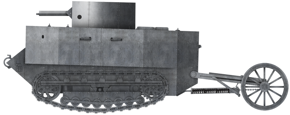
Illustration showing how the Lincoln No.1 Machine might have looked during its tests without the canvas cover. Behind it is the Foster Daimler tractor, from which the engine, transmission and front wheels were reused on the tank. Illustration by Tony Bryan, taken from British Battle Tanks: World War I to 1939 by David Fletcher.

The Lincoln No.1 Machine during trials. The two openings at the front are clearly visible, although the hatches themselves seem to be missing. This photo shows the outer side of the tracks, which were of poor quality. Photo: IWM Q 14542
Little Willie specifications |
|
| Dimensions (L-w-h) | 5.87×2.86×2.51 m (19x9x8 feet) |
| Total weight, battle ready | 16.5 tons |
| Crew | 6 |
| Propulsion | Foster-Daimler Knight sleeve valve petrol 105 hp |
| Speed | 3.22 km/h (2 mph) |
| Range/consumption | 30 km/800 liters (18.64 mi) |
| Armament | Vickers 2 Pdr (40 mm) Mk.II 6 Vickers 7.7 mm (0.303 in) machine guns |
| Armour | From 10 to 15 mm (0.39-0.59 inches) |
| Total production | One prototype |
Sources
‘The British Tank: 1915-1919’ by David Fletcher
‘Osprey New Vanguard 100, British Mark I Tank 1916’ by David Fletcher
‘AFV Weapon Profiles 3, Tanks Mark I to V’ by Chris Ellis and Peter Chamberlain
‘A New Excalibur: The Development of the Tank, 1909-1939’ by A.J.Smithers
‘The Tank: Its Birth and Development’ by William Foster and others
‘The Landships of Lincoln’ by Richard Pullen
‘Eyewitness, being personal reminiscences of certain phases of the Great War, including the genesis of the tank’ by Major-General Sir Ernest D. Swinton.
‘History of the Tank’. Dinner Speech on the Commemoration of 50 years since the first use of tanks. January 1977
‘Lincoln No.1 Machine, Little Willie’ by M.J.Verrall, October 1988
‘The Madsen Machine Rifle. Main Characteristics, Organization and Tactical Use’
The Commercial Motor, A SIX – CYLINDER 105 h.p. SLEEVE-VALVE DAIMLER, 3rd April 1913, Page 14
The Commercial Motor, 3rd April 1919
This entire article has been funded by our Patron Golum through our Patreon campaign!

The Lincoln No.1 Machine, sporting the round turret armed with a 2-pounder Pom-Pom gun. Two more Madsen machine-guns are sticking out of the side sponson ports. Illustrated by Bernard ‘Escodrion’ Baker, funded by our Patron Golum through our Patreon Campaign.

Little Willie – Tank Encyclopedia Support Shirt
Little Wille, the first tank prototype, features prominently in this snark shirt! A portion of the proceeds from this purchase will support Tank Encyclopedia, a military history research project.
Col. R.E.B. Crompton (Pioneers of Armour)
By Andrew Hills
The foundations and principles of modern armoured warfare did not appear out of a vacuum, and nor did the machines of WW1 and WW2. Their development was full of false starts, failed ideas, and missed opportunities. Rookes Evelyn Bell Crompton was a pioneer in electrical engineering and road haulage who, by the turn of the century found himself in South Africa during the Boer War. Later, in WW1 his early work with the Landships Committee on tracked vehicles sought to break the stalemate of trench warfare. Although his tank designs never saw combat the work he started was carried on by other pioneers and helped to usher in a dawn of armoured and mechanised warfare.
3 replies on “Lincoln No. 1 Machine”
“A close examination of the image shows that the first roadwheel has already disconnected with the tracks.”
If you look closer you will note that the idler is coming off the track as well and had they not stopped the whole track would have been thrown.
Tank designers were addicted to adding machine guns wherever possible in WWI
Well, you do need it with the hundreds of soldiers in the trenches it was meant to cross, and firing AP shells won’t help a lot