 German Reich (1935)
Medium Support Tank – 35 Built
During the early development of the Panzer IV, no one involved in the program knew that this vehicle, designed to serve as a support Panzer, would become the Wehrmacht’s backbone for a good deal of the war. While today the Tiger and Panther are better known, the Panzer IV was produced in the greatest numbers and served on all fronts in many bloody engagements throughout the war. The development of this tank began in the mid-thirties, leading to the first model, the Panzer IV Ausf.A, being built. While this version was built in small numbers, it was more important as a starting point for the German designers in gaining valuable experience with this kind of vehicle.
Initial German Tank Developments
During the twenties, the German army began showing interest in the development and construction of tanks (Panzer in German), despite such a thing being banned by the Treaty of Versailles. One of the earlier attempts was the Leichttraktor (light tractor) armed with a 37 mm anti-tank gun. Beside this project, there was also a series of so-called ‘Grosstraktor’ (large tractor) built and tested in the late twenties which were armed with larger 7.5 cm guns. Another example was the ‘Neubaufahrzeug’ (new construction vehicle) built in 1934. The names of these vehicles may seem a little odd at first, but they were given in order to deceive the Western Allies about their actual purpose. The Germans were at this time still forbidden from developing and producing tanks. These vehicles were built in small numbers only and were used primarily for testing and gaining valuable experience in tank construction.

One of the main problems encountered with the development of these earlier vehicles (especially the Neubaufahrzeug) was the use of modified aircraft engines. These engines produce very high torque at low speeds (1400 to 1600 rpm) which forced the Germans to use heavier drives than otherwise needed. Due to restrictions in weight (in order to cross bridges), the armor had to be thinner, the crew had to be smaller and the size of the gun was limited. Other issues included the overcomplicated suspension and the position of the drive sprocket.
In order to solve these issues, Wa Pruef 6 (the German armor design office which was part of the ordnance department) insisted that, for the new series of medium Panzers initially named ‘Verbesserten Neubau Fahrzeug’ (Improved New Construction Vehicle), a specially designed engine would be used. The well known Maybach factory was chosen as it had experience in engine development from its production of Zeppelin airship engines. In addition, great attention would also be given to the development of an improved suspension system. From these demands appeared the Begleitwagen, from which the future Panzer IV would eventually arise.

Name
‘Begleitwagen’, shortened B.W., can be translated as escort vehicle, or even as escort tank. Although it is quite common in modern sources to see B.W. being taken to mean ‘Bataillonfuehrerwagen’ (battalion commander’s vehicle), the use of this term dates from Rheinmetall wrongly designating the B.W. as ‘Bataillonwagen’ (battalion vehicle) in 1943. Post-war historians reused this term and added on the ‘fuehrer’ to create the incorrect ‘Bataillonfuehrerwagen’ designation. In any case, the initial use of the Begleitwagen designation was meant to hide the true purpose of this vehicle from the rest of the world, as the development of tanks was forbidden by the Treaty of Versailles.
In March 1935, the German government officially decided to publicly renounce the Treaty of Versailles. For this reason, there was no more need to disguise the true nature of these vehicles. The initial name Begleitwagen would be replaced with Gesch.Kpfw. (75 mm) Vs.Kfz.618 (Geschütz Kampfwagen 75 mm Versuchs Kraftfahrzeug 618 – 75 mm Gun Tank Test Vehicle). On 3rd April 1936, the name was changed to Panzerkampfwagen IV (75 mm) Vs.Kfz.622. This vehicle would also receive the Ausführung (version or type) A (Ausf.A for short) suffix to distinguish it from later models. Most sources use the much simpler Panzer IV Ausf.A designation. This article will use this shorter term for the sake of simplicity.
Development of the Support Tank Concept
The development of the medium Panzers was already underway during the early thirties. In top military circles, which included Generalmajor Oswald Lutz and his Chief of Staff Oberstleutnant Heinz Guderian of In 6 (Inspektorat 6, the inspectorat for mechanization), two new Panzer concepts were being formed. One was to be developed to counter enemy tanks, named Z.W., ‘Zugführerwagen’ (platoon commander’s vehicle). Initially, this vehicle was to be armed with a 3.7 cm gun.
The second concept was to act as a support vehicle for the Z.W., with a larger caliber gun firing mostly high explosive ammunition. For this reason, the B.W. was to be equipped with one 7.5 cm gun which would enable it to destroy enemy bunkers, anti-tank guns and machine-gun nests. Additional requirements for the B.W. were an overall weight of 18 tons, armor thickness between 5 and 14.5 mm, being powered by a 320 hp engine, a top speed of at least 30 km/h, dimensions of around 5600 x 2900 x 2650 mm, the ability to cross 2.2 m-wide trenches and to climb a 30° slope. The last requirement regarded the ammunition capacity, calling forth 140 rounds for the main gun and 3000 rounds for the machine guns. The work on the B.W. was officially approved by In 6 on 25th February 1934. Two firms, Rheinmetall and Krupp, would compete to design this vehicle.
The Unsuccessful Rheinmetall Begleitwagen
Rheinmetall had been involved in the earlier Panzer development program and was, for unknown reasons, favored by Generalmajor Lutz. In 1932, he insisted that the development of Panzers should be given to one firm only: Rheinmetall. This company designed and built the Neubaufahrzeug, which proved to be an unsuccessful and outdated design. Despite this, Rheinmetall received a contract in February 1935 for building the first prototype for the new B.W. vehicle.
The resulting design weighed 18 tons, with 13 to 20 mm of armor. Its armament consisted of a 7.5 cm gun and two machine guns. With its 300 hp engine, the maximum speed was estimated to be around 35 km/h. This vehicle had a running gear which consisted of eight small road wheels connected in pairs, three return rollers (on each side), two front driver sprockets and two idlers. The suspension design was more or less taken from another Rheinmetall vehicle, the Neubaufahrzeug. One wooden model and one soft steel vehicle were built, but no production orders were given and the design was rejected.

The Krupp Design
The Krupp company was also involved in the initial steps of designing Panzers, but was also involved in designing and building the turret for the Rheinmetall Neubaufahrzeug. In later years, the Krupp company would be the chief turret designer for most German tanks during the war.

During April 1934, Krupp offered the German army two different projects for the B.W. requirement. Both vehicles were to be armed with the same 7.5 cm main gun and two machine guns. The first was designed as a 17.2 ton tank with 20 mm of frontal and 14 mm of side armor. The second one was somewhat heavier (18.5 tons), having thicker 30 mm front and 20 mm side armor. There was also a proposal to add a secondary sub-turret (possibly armed with two machine guns), possibly on the right side of the superstructure, somewhat similar to the Rheinmetall prototype. Great attention was given to the development of the suspension and, after a series of trials, two models were proposed, using eight wheels or six larger ones.

In July of 1935, Krupp received an order to produce one B.W.I Kp (with eight road wheels) prototype vehicle. In October the same year, another order was given for the production of the B.W.II Kp (with six road wheels). In January of 1936, Krupp received orders for the production of the B.W. superstructure, main turret and smaller sub-turret.
A fully operational B.W.I Kp was completed by the end of April 1936. Shortly after, the B.W. II Kp prototype without the turret was also constructed. The fate of the sub-turret variant is not clear but it is possible that it was never implemented on any Krupp prototype. While neither of these two vehicles would enter serial production, the B.W.I Kp would, with a number of improvements and modifications, be used as base for the future Panzer IV. Both prototype vehicles would be used for testing and evaluation, including trials of bridge-laying equipment.


Connection to the VK20.01 Series
In some sources (like D. Nešić, Naoružanje Drugog Svetsko Rata-Nemačka, for example), it is noted that the Panzer IV was actually based on a series of experimental armored vehicles called VK20.01 (VK is for Vollketten – fully tracked). It is important to note that this is not exactly true, mainly due to the fact that the VK20.01 project was initiated in 1938 as a replacement for the Panzer III and IV. In addition, the aforementioned Rheinmetall B.W. prototype was never called VK20.01(Rh) by the Germans at that time.
The Panzerkampfwagen IV
The German army officials were generally satisfied with Krupp’s B.W.I prototype and asked for a small series of improved ‘1.Serie/B.W.’ (1./B.W.) to be built. The new vehicle was visually the same as the B.W.I prototype, but with many improvements and modifications. Some of these included the almost complete use of welding for the armor, a different commander’s cupola, a modified superstructure, adding a stronger and larger 230 hp@ 2600 rpm Maybach HL108 TR engine, changing the shape of the drive sprocket and idler, and several other more minor adjustments.

Production
Production of the first Panzer IV was carried out by Krupp-Grusonwerk from Magdeburg-Buckau. It began in October 1937 and, by March (or June depending on the source) 1938, all 35 vehicles were completed. Despite the general misconception nowadays that the Germans had a well developed and advanced industry, in reality this was not exactly the case. The long time to build just 35 vehicles is proof of this, as Krupp simply had no capacity (at least prior to the war) for mass production of tanks. The chassis numbers of these vehicles run from 80101 to 80135.
Specifications
The Hull
The Panzer IV hull was divided into the rear engine compartment, the central crew compartment and the forward-mounted transmission and enclosed driving compartment. The lower part of the hull had 10 different sizes of openings to allow easier maintenance for the crew. In the case of an emergency, the crew could use the round escape hatch door located beneath the radio operator’s seat. The front hull was where the transmission and steering systems were placed and was protected with an angled armor plate. To gain better access for repairs, a square-shaped transmission hatch located in the middle of this plate and two rectangular steering brake inspection hatches were added.
The Superstructure
The superstructure was added atop the Panzer IV hull to provide sufficient protection for the crew members. To provide sufficient working space and ammunition storage, it was wider than the hull. It consisted of four welded plates (one at the front, one on each side and one at the rear) and the armored roof plates. The front plate was not flat, with the driver plate protruding out. This was done to provide the driver with a better view to the front and sides when driving. On the front side of this plate, a protective driver’s visor port was placed, which was provided with thick armored glass for extra protection. When this visor was closed (usually when in combat operations), the driver would then use the KFF binocular periscope to see through two small round ports located just above the visor port. On the right side of the protruding driver plate, an observation hatch with no visor was placed. In front of the radio operator’s position to the right of the front plate was a ball mount for a machine gun.
The side armored plates were placed vertically and were curved inwards toward the front plate. A visor port was added on each side. On the left side, there was a ventilation opening for the steering brakes. To protect this vulnerable spot, an armored covering was added. The engine and the crew compartment were separated by a fire resistant and gas-tight armored firewall.
The roof armor plate was mostly flat, beside the front part (above the driver and radio operator), which was angled slightly downwards. To gain access to their position, the driver and the radio operator were each provided with a two-part hatch located on the front roof armor. Each of these hatch doors had a small round port for the use of signal flares.

Interestingly, the last five produced Panzer IV Ausf.A had a new redesigned Panzer IV Ausf.B hull, which had 30 mm of frontal armor. In February 1941, all surviving Panzer IV Ausf.As were reinforced with additional 30 mm thick front plate armor.

The Turret
The Panzer IV Ausf.A turret had a front hexagonal-shaped armor plate with two small observation hatches placed on either side of the centrally positioned main gun. Each of the turret sides had observation vision ports and a one-piece hatch for the crew. For protection against infantry attack, the turret had two square shaped machine gun ports located on the rear curved armor plate. To provide a good ventilation for extraction of propellant fumes, a ventilation flap was installed on the turret top. Inside the Panzer IV Ausf.A, an auxiliary DKW gasoline engine was provided to power the electric engine that was used to traverse the turret. A round fuel supply opening for the DKW engine, was placed on the rear left of the superstructure roof. The turret was, from March 1941 on, provided with a large stowage box mounted on its rear.
At the rear of the turret, a commander’s cupola was placed. The commander’s cupola had a simple drum shape and eight small vision slits. These slits were protected with 12 mm thick armored glass which offered the commander limited protection from bullet splash. On top of the cupola, a two-piece hatch door was installed. Its purpose was to allow the commander to enter his position, but also to provide a good all-around view when not engaged in combat.
The Panzer IV Ausf.A had a turret ring with a diameter of 1680 mm. This turret ring was provided with ball bearings which would allow the turret to rotate freely. The small opening between the turret and the superstructure was protected with angular shaped deflectors.

In order to implement a kind of standardisation between different Panzer vehicles, the Panzer IV Ausf.A used vision ports taken from the Panzer II Ausf.A. In addition, the commander’s cupola was taken from the Panzer III Ausf.B vehicle.
Suspension and Running Gear
During the development of the Krupp prototype that would eventually lead to the Panzer IV, at least five different suspension systems were tested, including a torsion bar suspension which was favored by some officials from the Wa Pruef 6. This suspension was tested on the B.W.II but proved to be a failure. The reason for this was the fact that each torsion bar had to be provided with a shock absorber. These absorbers were often prone to overheating, which led to problems with the suspension. For this reason, Krupp’s chief tank designer Ober.Ing. Woelfert insisted on using a self-dampening leaf spring suspension. While it was not perfect, it had a much simpler design and was easier to build. Another advantage of this leaf spring suspension was the ease of field repair in case of a malfunction or combat damage.
The suspension consisted of eight small (470 x 75 x 660 mm) wheels placed on each side, suspended in pairs and placed on four bogie assemblies. The small road wheels were suspended by leaf-spring units. The distance between each bogie shaft was 500 mm. There were also four return rollers (250 x 65 x 135 mm) on each side. At the front, two drive sprockets (with 18-teeth) were placed, and on the reinforced back hull two idlers were positioned. The tracks used on the initial production Panzer IVs were 360 mm wide and were connected using pins. The ground clearance of this vehicle was 40 cm. For a vehicle weighing 18 tonnes (or 17.3 tonnes depending on the source), this suspension system was considered adequate, but proved to be problematic later in the war due to the extra added weight of following upgrades.

The Engine and Transmission
The engine used on this vehicle was the Maybach HL 108TR which produced 230 hp@2600 rpm. The maximum speed was 32 km/h (or 10 km/h cross-country) with an operational range of 210 km and 130 km cross country. The fuel load of 470 l (or 453 l or depending on the source) was stored in three fuel tanks placed under the crew fighting compartment. If needed, there was a valve system that allowed the crew to use the fuel of each tank individually by closing the fuel supply from the other two.
The Panzer IV’s engine cooling system consisted of two coupled radiators placed at a 25° angle. The air was then sucked in by two large cooling fans which were driven by a ‘V’ shaped belt from the crankshaft. This cooling system was designed to provide effective cooling in temperatures of up to +30° Celsius. The engine and the crew compartment were separated by a fire resistant and gas-tight armored firewall. The crew could, if needed, gain access to the engine through a door placed at this firewall.
The ‘Allklaunen SFG 75’ five-speed (and one reverse) transmission was connected to the engine by a drive shaft that ran through the bottom of the fighting compartment. The steering mechanism used in the Panzer IV Ausf.A was of the ‘Wilson’ type, which was designed and produced by Krupp.
The Panzer IV Ausf.A turret was not centrally positioned and was actually offset to the left side of the superstructure by around 6.67 cm. The engine was also offset some 15 cm to the right. This arrangement was done so that the driveshaft did not interfere with the electrical supply system of the turret.
The Armor Protection
The general armor protection of the first Panzer IV Ausf.A was rather weak, ranging between 8 to 16 mm. For the lower hull, the upper front armor plate was 10 mm thick at a 72° angle, and the lower plate was 14.5 mm placed at a 14° angle. The side armor was 14.5 mm thick, the rear was 10-14.5 mm and the bottom was 8 mm.
The front hull armor was 14.5 mm placed at a 9° angle. The sides of the crew compartment were 14.5 mm placed vertically. The engine compartment was protected by 10 mm thick armor (at a 35° angle) at the sides and 14.5 mm (at 10° angle) to the rear.
The front turret armor was 16 mm (at a 10° angle), while the sides and rear were 14.5 mm (at 25° angle) and the top was 10 mm (at 83-90° angle). Depending on the source, the front armor thickness of the turret varies between 15 to 20 mm. The commander’s cupola had all-around 14.5 mm of armor, with the two hatch doors being 8 mm thick.
The armor plates were made using nickel-free homogeneous and rolled plates. The Panzer IV Ausf.A armor was designed primarily to provide protection from 7.92 mm armor piercing bullets usually fired from anti-tank rifles. The anti-tank rifles were a typical infantry weapon to fight tanks in the thirties and in the earliest stages of the war. The Panzer IV Ausf.A armor provided almost no protection from any larger caliber anti-tank guns.
From August 1938 on, nearly all German Panzers were equipped with a Nebelkerzenabwurfvorrichtung (a smoke grenade rack system). This device was placed on the rear of the hull. This rack contained five grenades which were activated with a wire system by the Panzer IV’s commander. When activated, the Panzer would then drive backward to the safety of the smoke screen. This system was not very effective and was replaced with turret mounted smoke grenade launchers later in the war.

The Crew
The Panzer IV had a crew of five which included the commander, gunner and loader who were positioned in the turret, and the driver and radio operator in the hull. This five man crew configuration was a rarity at that time and provided the Germans with a huge advantage during the earlier stages of the war.
The Panzer IV commander (Kommandant) was positioned in the rear center of the turret. For observing the surroundings, he was provided with a cupola. For crew communication, the commander was provided with an intercom system in the form of a laryngophone.
During the early testing with the Grosstraktor (held in Kazan in the Soviet Union), the Germans noted that the commander should not be involved in any duties beside his intended role, such as loading or firing the gun. If the commander was distracted, the overall performance of the Panzer would be much reduced, as he could not pay proper attention to his surroundings (for example the position of friendly or enemy units.). For this reason, the commander was provided with a cupola that had an all-around view and was tasked with directing the whole crew. This simple innovation gave the Germans a huge tactical advantage in the earlier stages of the war. For example, French and Soviet tank commanders also had to perform other roles like serving the gun and even loading, which greatly diminished the performance of their tanks despite having better armor and weapons than the Germans.

The gunner (Richtkanonier) was positioned to the left while the loader (Ladekanonier) was to the right of the main gun. While not in combat, the loader could use a folding seat on the right side of the turret. Once in combat, in order to get the stored ammunition, he would simply fold the seat to the side and then stand on the turret basket floor.
The driver’s position (Fahrer) was on the front left side of the hull. The last crew member was the radio operator (Funker), who was positioned on the front hull’s right side. His main job was to operate the Fu 6 and Fu 2 transmitter-receiver radio set, which had an effective range of about 2 km. This radio was mounted just above the transmission. A folding 2 m long antenna rod with its wooden protective rail was placed on the Panzer IV’s right superstructure side. The secondary duty of the radio operator was to use the hull mounted 7.92 mm MG 34 machine gun.
The Armament
The main armament of the Panzer IV Ausf.A was the 7.5 cm KwK 37 L/24. KwK stands for ‘Kampfwagenkanone’ which could be translated as combat vehicle cannon or, more simply, as tank gun. The short barrel had 28 grooves, each 0.85 mm deep. It had a semi-automatic breech, which means that, after firing, the spent cartridge would be self-ejected, thus increasing the overall firing rate. The Panzer IV Ausf.A had an internal gun mantlet which was not too effective. Later Panzer IV versions had an external mantlet which provided better protection. The gun recoil cylinders that stood outside of the turret and the gun were covered by a steel jacket and a deflector guard. For the gunner’s protection, a recoil shield was added to the rear of the gun. On a number of Panzer IV Ausf.A (and even later models), a ‘Y’ shaped metal rod antenna guide was added under the gun. Its purpose was to deflect the antenna and thus avoid damaging it during turret rotation.

This gun had a muzzle velocity of 325 m/s and proved to have satisfactory precision in combat operations and was even used to arm the early series of the StuG III vehicles. The Panzer IV Ausf.A was primarily meant to destroy soft skin targets, anti-tank positions etc. and was thus mostly equipped with high explosive and smoke rounds. The armor piercing (AP) round could penetrate 41 mm of armor sloped at 60° at 100 m. At ranges of 500 m, the penetration dropped to 38 mm. The elevation of this gun went from –10° to +20° (–10° to 30° depending on the source). Originally, the ammunition load consisted of 140 rounds but was reduced to 122 rounds from December 1938 on in order to reduce weight. The ammunition was stored in holding bins located on the hull sides and floor.

This gun was equipped with a TZF5b ‘Turmzielfernrohr’ monocular telescopic gun-sight. This sight had a magnification of 2.5 and a field view of 25°. For aiming at the target, this gun sight had two engraved reticles. In the centre of the first engraved reticle there was one large aiming triangle with smaller ones on both sides. The gunner had to aim the larger triangle at the enemy target, while the purpose of the smaller ones was to help in determining the target’s speed. This gun-sight was quite complicated to use, and required that the gunner be well trained. The second reticle was used to help the gunner adjust the main gun to the necessary range. In combat, the gunners learned to simply use the turret coaxial machine gun to determine the range to the target. The Panzer IV Ausf.A was also provided with a clinometer for indirect fire support.
Under the telescopic sight there were two mechanical hand wheels for elevation and traverse of the main gun. The trigger for the 7.5 cm gun was located on the traverse handwheel. The turret was traversed via an electric motor located on the left side of the turret. Minimum traverse speed was 0.14° while the maximum speed was 14° per second. When the gunner engaged the traverse, the turret moved abruptly, which made it somewhat difficult to track moving targets. If, for some reason (either combat damage or mechanical breakdown), this motor stopped working, the turret could also be manually traversed. There was a selector lever which switched between these two systems depending on the needs. While the gunner would operate the manual traverse of the turret, there was a larger hand crank that the loader could use. By using manual traversing, the gunner could rotate the turret by 1.9° and the loader 2.6° per turn.
Beside the main gun, the Panzer IV Ausf.A was provided with two 7.92 mm MG 34 machine guns for defense against infantry. One was mounted in a ball mount in the hull and was operated by the radio operator. The second machine gun was placed in a coaxial configuration with the main gun and was fired by the gunner. The ammunition load for the two MG 34’s was 3000 rounds. There was an option for installing an anti-aircraft machine gun mount on the Panzer IV Ausf.A, but its use was discarded in early 1938 and it was never used in combat.
Organization and Tactics
Prior to the German invasion of Poland, the general organization of a Panzer Division consisted of two regiments each having two Panzer Battalions. These battalions were then divided into four companies. Although these units were meant to be equipped with modern Panzer III and IV tanks, due to the slow rate of production, this was not possible. For this reason, the earlier Panzer Divisions had to be equipped with weaker Panzer I and II tanks, and even captured vehicles like the Panzer 35 and 38(t). In the case of the Panzer IV, the situation was so critical that each Panzer Division could only be equipped with 24 (on average) such vehicles. The few produced Panzer IV were allocated to the so-called Heavy companies, which were divided into two platoons each with 3 vehicles.
The primary function of the Panzer IV was to provide covering and suppressing fire for the advancing Panzer units. While they were used in Heavy companies in combat situations, the battalion commanders would often reallocate the Panzer IV to other companies. These mixed units offered better cooperation between different types of Panzers, as the identification of targets could be achieved easier. Then, the Panzer IV crews could direct their firepower to destroying the marked target much quicker.
The usual German Panzer tactic was the use of the ‘Keil’ (wedge) formation. The tip of this attack would be formed by the Panzer III and Panzer 35 and 38 (t), while the Panzer I and II would advance on the flanks. The Panzer IV were to follow up, and would continue destroying any marked targets. The targets would usually be marked with tracer rounds or smoke marker shells. The Panzer IV’s 7.5 cm cannon was effective against all soft skin targets, but was also effective against most tanks except for the better-armored ones like the French Char B1 or British Matilda II.
In Combat
The first two completed Panzer IV Ausf.A were given to the Waffenamt inspectors by the end of November 1937, with the last vehicle being accepted in June 1938. Before the war, the Panzer IV Ausf.A was used on military parades. They were also employed during the Anschluss of Austria and the occupation of Sudetenland.
Due to the low production capabilities of the German war industry by the time of the outbreak of the war, only 211 Panzer IVs were available in September 1939, including 30 Ausf.A, the remaining 5 being used for testing. At the end of the Polish campaign, 19 Panzer IV had been destroyed with 50 more being damaged or out of action either due to mechanical breakdowns or enemy fire. In Poland, the Panzer IV Ausf.A, while effective in its original role, proved to be vulnerable to nearly all enemy anti-tank weapons because of its weak armor. On the other hand, the gun could easily destroy any Polish armored vehicle, being themselves only lightly armored.
The Panzer IV Ausf.A saw action in Norway and also participated during the German offensive in the West in May 1940. The surviving Panzer IV Ausf.A remained in use up to the spring of 1941, when they were (mostly due to the very weak armor) removed from service and given to training units.


Conclusion
Viewed from today’s perspective (with the hindsight of what happened during the war), the development of two significantly different types of tanks which were to perform different roles on the battlefield seems odd at best. The development of one vehicle capable of performing both anti-tank and support roles (eventually two variants of the same vehicle) would have been a much easier solution. It would have made production faster and reduced the need for production of two types of spare parts.
The development of a support tank led to the Panzer IV Ausf.A being built. While it was lightly armored, it had a five man crew, good mobility, solid firepower and, with modern tactics, showed that this concept had merit in the earlier years of the war. Despite the fact that the later versions of the Panzer IV would become capable of filling both roles, the first model Panzer IV Ausf.A was one of the earlier first steps in the development of the famous Panzer Formations.
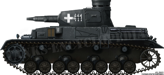
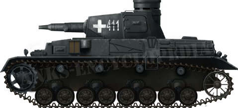
A Panzer IV Ausf.A, Poland, 4th Company, 1st Abteilung, 1st Panzer Regiment, 1st Panzerdivision. Illustration by Tank Encyclopedia’s own David Bocquelet
Specifications |
|
| Dimensions (l-w-h) | 5.92 x 2.83 x 2.68 m (17.7 x 6.11, 8.7 in) |
| Total weight, battle-ready | 18 tonnes (39,683 lbs) |
| Crew | 5 (Commander, Gunner, Loader, Radio Operator and Driver) |
| Propulsion | Maybach HL 108TR 230 HP @ 2600 rpm |
| Speed (road/off road) | 32.4 km/h, 10 km/h (cross country) |
| Range (road/off road)-fuel | 210 km, 130 km (cross country) |
| Primary Armament | 7.5 cm KwK L/24 |
| Secondary Armament | Two 7.92 mm MG 34 |
| Elevation | -10° to +20° |
| Turret Armor | front 16 mm, sides 14.5 mm, rear 14.5 and top 8-10 mm |
| Hull Armor | front 10-14.5 mm, sides 10-14.5 mm, rear 14.5 mm and the top and bottom 8-10 mm. |
Sources
K. Hjermstad (2000), Panzer IV Squadron/Signal Publication.
T.L. Jentz and H.L. Doyle (1997) Panzer Tracts No.4 Panzerkampfwagen IV
T.L. Jentz and H.L. Doyle (2001) Panzer Tracts No.20-1 Paper Panzers
D. Nešić, (2008), Naoružanje Drugog Svetsko Rata-Nemačka, Beograd
B, Perrett (2007) Panzerkampfwagen IV Medium Tank 1936-45, Osprey Publishing
P. Chamberlain and H. Doyle (1978) Encyclopedia of German Tanks of World War Two – Revised Edition, Arms and Armor press.
Walter J. Spielberger (1993). Panzer IV and its Variants, Schiffer Publishing Ltd.
D. Doyle (2005). German military Vehicles, Krause Publications.
S.J. Zaloga (2011) Panzer IV vs. Char B1 Bis, Osprey publishing
A. Lüdeke (2007) Waffentechnik im Zweiten Weltkrieg, Parragon books.
7 replies on “Panzerkampfwagen IV Ausf.A”
The first truly modern tank.
Such a beautiful tank
A wide range of AP ammunition was developed for the 75mm. L.24 KwK.37 gun.
K.Gr.Rot Pz. (APHE) = 48mm. @ 0 degrees @ 100 metres. (Poland 39)
PzGr.39 (APCBC-HE) = 57mm. @ 0 degrees @ 100 metres. (France 40)
PzGr.40 (APCR) = 76mm. @ 0 degrees @ 100 metres. (From 41)
Gr.38.HL/A (HEAT) = 84mm. @ 0 degrees @ all ranges.
Gr.38.HL/B (HEAT) = 91mm. @ 0 degrees @ all range.
Gr.38.HL/C (HEAT) = 120mm. @ 0 degrees @ all ranges.
(From Kummersdorf range tests).
nice. :]
The article says that the loader had a “hand crank” for rotating the turret. That’s not true for the Ausf.A. The hand crank for the loader didn’t arrive until the “long” gun was used in the Panzer IV.
Was it ever equipped with add on armor as model kit Dragon 6816?
I’d be interested to know what would be a normal ammo mix for a Pz4. IE: how many HE, HEAT etc.