 United States of America (1968-1969)
Civil Engineering Vehicle – 1 Built
Background – The Cross Florida Barge Canal: “The Ditch of Dreams”
As far back as 1565 with Governor Pedro Menéndez de Avilés, when Florida was ruled by Spain, people have dreamed of cutting a waterway across it to shorten the voyage to the Gulf of Mexico from the east coast of America and from Europe. United States territorial governments in Florida first started considering a canal in the 1820s, with the first legislation being the Canal Memorial sent to Congress in 1825. Andrew Jackson (President of the United States, 1829-1837) had supported the idea of a canal during his tenure as Governor of Florida in 1821, but he did not condone the use of taxpayers’ money for the project as President, and the project was rejected as unfeasible.
The next attempt to build a canal across the width of Florida after the failed 1820 motion, was during the Great Depression. Calvin Coolidge’s River and Harbor Act of 1927, which ordered the US Army Corps of Engineers to carry out surveys, the cost of which had been determined two years prior, would form the basis for the project which would see the first breaking of ground on a cross-Florida canal. After extensive lobbying and political squabbling, in 1935, President Franklin D. Roosevelt approved the use of 5 million dollars to construct the Atlantic-Gulf Ship Canal, which would provide jobs as part of his New Deal program.
Route 13B was chosen as the path for the canal. It would run from Palatka to Yankeetown via the St. Johns, Ocklawaha, and Withlacoochee rivers. The St. Johns River, and to a lesser extent, the Ocklawaha River, had been important transport and trade routes for much of Florida’s history. The St. Johns is a wide river providing access from the Atlantic Ocean to the cities of Jacksonville and Palatka. The Ocklawaha River is a much smaller, winding tributary of the St. Johns, which feeds into the latter just north of Lake George. The Ocklawaha meanders its way further inland before turning South and continuing all the way to Lake Griffin, near Leesburg. Before railways were built, the Ocklawaha had been the route connecting Lake Apopka with Jacksonville and the ocean. The Withlacoochee is on the other side of Florida; emptying into the Gulf of Mexico near Yankeetown. It runs inland and then south to Green Swamp. Green Swamp also happens to feed the Ocklawaha, though indirectly. Had the canal been finished, the two halves would have come together south of Ocala, Florida.

Map of the would-have-been Cross Florida Barge Canal, made in January 1971 Source
Construction began in 1935. The canal was to be a sea level canal, meaning it would cut straight through any mountains or hills along its path, and would not require any locks to change ships’ elevation. Due to political opposition from Secretary of the Interior Harold Ickes, who claimed that a sea level canal would destroy Florida’s aquifers, work on the canal was cancelled within a year. Other political factors also contributed to the cancellation of the Atlantic-Gulf Ship Canal, such as a need for disaster relief elsewhere in Florida, and pressure from the railroads and the city of Miami. The Depression Era canal attempt ended with only a few miles of ditches dug, some abandoned structures, and $5.4 million in wasted federal appropriations.
The cross-Florida canal idea was revisited in 1942 as World War II was in full swing and thousands of tons of shipping were being lost to German U-boats off the coast of Florida. The canal was proposed as a means for ships to avoid the U-boat infested waters of the Atlantic when making trips from the US East Coast to the Gulf of Mexico. Construction of the canal was approved as a wartime defense measure, however, Congress was still divided on it, ending in a tie that was only settled in favor of the canal by Vice President Henry Wallace. Despite being approved, the canal was never funded; unsurprising considering the mixed response from Congress in the first place. Political pressure also influenced this decision, as there was concern that had a canal been built it would rob port traffic from Palm Beach, Fort Lauderdale, and Miami. However, the men who served in World War II, and saw the loss of life at the hands of the U-boats first hand, would remember the government’s indifference to what they saw as a life-saving measure. Some of them would go into politics and would ascertain the third and final attempt at a canal in the 1960s.
Approved in 1963 by President John F. Kennedy, work started in 1964 under President Lyndon B. Johnson, the Cross Florida Barge Canal project was born out of a political struggle much too in depth to cover here. The project would run from 1964 to 1971 and follow much the same route that the 1930s canal would have. It was intended that the canal would benefit central Florida militarily, economically, and recreationally. The US Army Corps of Engineers was put in charge of construction of the canal and broke ground in February, 1964.
Only two locks, Buckman and Inglis, were completed on the Cross Florida Barge Canal, with a third, Eureka, left unfinished. The first lock built was originally known as the St. Johns Lock, but was renamed Henry H. Buckman Lock, or simply Buckman Lock. Buckman Lock is the closest lock on the canal to the St. Johns River. It sits on a man-made portion of the canal connecting Rodman Reservoir and the St. Johns, bypassing the lower Ocklawaha. Buckman Lock is less than two miles (about 3 kilometers) from the St. Johns River and 4.75 miles (7.64 km) from Rodman Reservoir. Construction began in 1964 and was completed in 1968. Buckman Lock is the lock for Rodman Reservoir, despite being some distance away from it.
Work on Rodman Dam and Eureka Lock and Dam began about the same time in 1966. Rodman Dam is roughly 7 miles (11.25 km) from the St. Johns River. Eureka Lock and Dam, named for the nearby town of Eureka, is 21 miles (33.8 km) upstream from Rodman Dam. Eureka Lock and Dam was entirely complete apart from a 400 foot (122 meter) section of the 4,000 foot (1,220 meter) wide earthen dam that was never filled in.
Work on Rodman Dam and Reservoir was conducted by the Army Corps of Engineers from 1966 until September 30th, 1968, when the dam was closed and the reservoir filled. Rodman Dam is about 7,200 feet (2,200 m) long, 300 feet (91 m) wide at the base, and 30 feet (9 m) wide at the top. It has a four gate spillway, each gate measuring approximately 40 feet (12.2 m) wide by 15 feet (4.6 m) tall. The gates can be lifted above the spillway to increase flow. The top of the dam is 28 feet (8.5 m) above sea level and 22 feet (6.7 m) above the surrounding natural ground elevation. The spillway crest is only 6 feet (1.8 m) above sea level. The spillway’s ‘apron’ (the flat, sloping, concrete path where the water leaving the spillway flows) is 100 feet (30.5 m) long, about 160 feet wide (48.8 m), and ranges in elevation from 3 to 15 feet (0.9 to 4.6 m) below sea level. The spillway discharge channel is nearly a mile long, has a depth of between 8 and 20 feet (2.4 to 6.1 m) depending on flow, and narrows from about 300 feet (91 m) to about 150 feet (46 m) before meeting what remains of the Ocklawaha River. The Ocklawaha meanders for another 11.6 miles (18.7 km) and then empties into the St. Johns south of the canal exit.
The only other completed lock is on the Gulf coast of Florida, near Yankeetown. The Inglis Lock and Dam is located on the Withlacoochee River, and holds back Lake Rousseau. Inglis Lock is the only portion of the Cross Florida Barge Canal to have seen use besides Rodman Reservoir. The lock has since fallen into disrepair and has not operated since 1999.
In total, the Cross Florida Barge Canal would have been 107 miles (172 km) long when completed. However, construction work was slow, and quickly fell behind schedule, probably not least in part due to lack of unified enthusiasm for the canal and public backlash. In an age when environmentalism was on the rise, seeing ancient forests destroyed and thousands of species of plants and animals threatened to make way for “more recreational waters” and a barge canal that was not really needed angered and divided the population. Marjorie Harris Carr, for whom the greenway that now spans the would-be area of the canal is named, led the public protest efforts against the canal for much of the losing battle. In the end, however, public outcry was too much to ignore, which led President Richard Nixon to sign an executive order to halt construction of the canal on January 19th, 1971.
The Monster from Fern Gully
Part of creating the aforementioned dams and the artificial reservoirs that would be held behind them was clearing the area of trees and other ground clutter. The goal was to have a central channel through the reservoir, of sufficient depth (12 feet / 3.65 m) to accomodate barge traffic. The area the channel would be cutting through on the Rodman and Eureka Reservoirs would be the general path once run by the flowing Ocklawaha. Area around the channel, which would soon be underwater if it wasn’t already marshland, would also need to be cleared to prevent underwater obstacles being swept into the barge lane, and to keep the area open for recreational pleasure craft. The task of clearing the swamp that occupied the area that was slated to become the Rodman Reservoir was especially daunting, in some places the swamp water was up to 6 feet (1.83 m) deep.
With this in mind, the Army Corps of Engineers asked for bids from civilian firms to do the clearing work. The barge channel was to be 400 feet (122 m) wide and 16.5 miles (26.55 km) long in Rodman Reservoir alone. 5,617 acres of land were to be cleared, 708 acres of that figure representing just the channel. The heavily forested section of Rodman Reservoir comprised 6,325 acres of ancient swamp forest. The time allotted for clearing the reservoir was a mere 445 days.
F. Browne Gregg, head of the company Gregg Gibson & Gregg, put in a very low bid; far too low in hindsight. With a bid 1 million dollars less than the next lowest bidder, Browne Gregg easily won the contract from the Army and was awarded $4,191,047. Soon though it was abundantly clear that doing the work traditionally of felling and removing thousands of acres of swamp and forest on the budget that the bid had given them would run the company a major loss. To get around this, Gregg came up with a novel solution; he would build a massive tracked vehicle, capable of going on land or water, that could be filled with water to increase its weight. The vehicle would weigh so much, and be so large, that with its sheer bulk it could push over trees up to 6 feet (1.83 m) in diameter, drive over them, stripping them of their branches and crushing the trunk and branches into the mud, where they would remain. Gregg hoped that this machine would save over a million dollars in clearing costs. The Crawler-Crusher was designed in only a few hours and perfected over only one weekend. It was designed to clear swamp at a speed of only half a mile per hour (0.8 kph), slightly slower for clearing dry land.
“I literally woke up from a sound sleep with ideas running through my head. I wasn’t thinking in words in my sleep but in moving pictures of machines and how I would utilize the equipment. I got up and went to the kitchen to brew myself a pot of coffee. By the time I had a hot mug in my hand, I knew what my first sketch would be. I had a draft board with a target light set up in my bedroom and I went to work.
I stayed at it, working on what I called the Crawler Crusher night and day. I was obsessed by the thing. I was oblivious to [my friend] Fred and his pal Jeff Cherry coming in and out of the bedroom. Jeff kept asking me, “What’s that you’re drawing, Mr. Gregg?” I ignored him as I was concentrating. He looked over my shoulder and watched what I was doing. He spoke right up and said, “Mr. Gregg, you forgot to put the hole on the top for the man to crawl into.” He was right and I told him I would get to it later. And sure enough, a few hours later, the boys were back, checking up on me. To them it was just a nifty army tank I was drawing for our military.”
-F. Browne Gregg on designing the Crawler-Crusher, taken from his autobiography Progress Through Innovation.
US Patent 3418961A, plainly entitled “Swamp Clearing Machine”, was filed by Frederick Browne Gregg of Leesburg, Florida, on behalf of Gregg Gibson & Gregg, Inc. on March 17th, 1967 and issued on December 31st, 1968, the machine itself having been completed at least several months prior. The dates surrounding its construction and operation are not known.

Crawler-Crusher patent Figures 2 and 4 respectively, showing the right side and right side cutaway of the machine. Source
In summary, the Crawler-Crusher is described by the patent as follows:
“It is a very large machine consisting of two large, hollow, watertight track pods. These pods can be separated for transport, and contain pumps that facilitate filling and draining them of water to control the weight of the vehicle. The design builds upon the armored, amphibious tree clearing machines in use by the US Army in Vietnam at the time. The Crawler-Crusher is superior to the Army’s tree clearers because it is fully amphibious and can regulate its ballast. While the Army’s tree clearers are at home on hard ground, sand, or open water, they struggle to operate in mud and marsh, where they bog down and cannot gain sufficient traction.”
The Crusher’s left and right track pods were mirror images of each other, but otherwise were identical. Each pod by itself measured roughly 50 feet (15.2 m) long, 12 feet (3.65 m) wide, and 12 feet 6 inches (3.8 m) high. Including the operator’s cabin, the entire machine stood 22 feet (6.7 m) high. For comparison, the largest tracked tank ever built (albeit unfinished), the K-wagen, measured 42 feet 8 inches (13 m) long and 19 feet 8 inches (6 m) wide.
Structurally, the Crawler-Crusher’s track pods were constructed and reinforced with hundreds of I-beams. Sixteen I-beams were oriented widthwise along the bottom of the pod, above the area containing the track rollers and their supports. The I-beams near the front and rear of the pod were tilted to follow the curvature of the bottom of the pod. There were two rows of short, vertical beams running down the center of the bottom of the pod between the two track roller channels, these supported the above mentioned 16 I-beams.
Above each of the 16 horizontal I-beams were 4 beams arranged diagonally which resembled a “W” shape when viewed as a cutaway from the front. The outermost arms of the “W” were placed in front, with the inner arms following immediately afterward. Each of these cross-beams was half the width of the I-beam they rested on, meaning they were all fully supported. In the center of each “W”, of which there were 16, one for each supporting I-beam, was another, shorter, vertical beam that separated the “W” in half. There were also occasional vertical I-beams placed directly against the inner and outer walls of the track pod, on either end of the “W”s; it is unclear from the blueprints whether these were continuous down the entire length of the track pod, if there were 16 of them and they were attached to the “W” frames, or if there was only a couple that were placed in specific areas.

Crawler-Crusher patent Figure 3, showing the vehicle from the front, the right side pod cutaway back to the partition wall midway down the length of the vehicle. Source
The four beams of the “W”, the central vertical beam, and the side vertical beams all supported a framework inside the pod that formed a floor, or “inner deck”. The height of the inner deck was at approximately 40% of the pod’s total height. Above the inner deck, extending to the roof, were over 100 vertical I-beam supports. There were 18 or 19 rows lengthwise down the pod, each row consisting of 7 beams widthwise. The outermost two beams in each row were placed directly against the outer and inner walls respectively. At the top of the pod, supported by the aforementioned vertical beams, was another framework of I-beams that support the roof and return rollers.
Entrance to the pod was via a side hatch, which was watertight and could be locked with two dogs (small, solid pieces of metal that are hinged on one side and can be flipped out to secure the door). The side entrance doors were hinged on the side facing the rear of the vehicle and opened outwardly. The entrance hatches were between rows 10 and 11 of the vertical I-beams (counting from the front). Directly across from the two exterior doors, on the inner walls of the pods, were two more doors. These allow travel and communication between the two pods when the machine is assembled. The inner doors were virtually identical to the outer doors, also being watertight and having locking dogs, but they are presumed to open inwardly. When the right side inner door is viewed from the inside, the hinges were on the right; the left side inner door is not illustrated or seen in any photos. The inner deck was partitioned off at beam row 10, dividing the interior of the pod into two large sections. Access to the forward compartment was via another hatch, identical to the side access hatch; it was placed between beam columns 3 and 4 (counting from outboard to inboard). For the right side pod, this hatch was hinged on the side facing outboard; again, the hatch in the left side pod is not seen in the blueprints.
Entrenched in the bottom of each pod were two channels containing the support rollers for the track. There were 188 rollers in total; the rollers themselves were the type normally used on Caterpillar D8 bulldozers. Each roller axle was supported by a pillow block bearing on either side, meaning there was no suspension at all. The roller itself was a cylinder with an enlarged band in the middle and flanged ends, this arrangement created two channels on the roller in which the track’s guide horns rested.
The return rollers on the top of the machine were nearly identical in construction to the support rollers, except for the fact that their ends had smaller flairs, and that the channels they rested in were not continuous along the entire vehicle. Each return roller had its own “well”, a recessed area it rested in. Each return roller well had a drain plug at the bottom underneath the roller, to let out rainwater. There were 4 top return rollers per channel, meaning 8 per pod, and 16 in total. At the back of the pod, above a small slanted rear roof section, were 2 more return rollers per channel, meaning 4 per pod, and 8 total. In total there were 12 return rollers on each track pod; 41 support rollers for each channel, 82 on each pod, and 164 total. For comparison, the TOG II* tank, known for its size and length, had only 32 support rollers in total.
The track links themselves were 11½ feet wide (3.5 m) and were made from a special steel alloy used by Caterpillar. Each track had a grouser of approximately 5 inches (127 mm) long, tapering from approximately 2.5 inches (63.5 mm) to 1.5 inches (38.1 mm) in girth. These long grousers gave the Crawler-Crusher a means of propulsion in the water, acting like paddle wheels. “Skids or wear strips” were placed along the bottom of the pod near the ends of the track links to support the outer length of the track and prevent them from bending and warping under the machine’s weight.
Propulsion for each track pod was provided by a Caterpillar D432 diesel engine, taken out of a Cat D8H bulldozer. Each engine produced 270 horsepower at the flywheel, for a total of 540 (FW) hp. Each engine, mounted on a support beam above the inner deck of its respective pod, drove a driveshaft that went through the rear wall of the pod, into a differential that took up the entirety of the rear of the pod beyond the rear wall. On either side of the differential was a large drive sprocket. The clutch for the differential was pinned in place, as it was only driving one large track instead of two smaller ones, and moving one sprocket more quickly than the other would be catastrophic. The patent remarks that even though the machine being built is powered by internal combustion, the design could accommodate any means of heavy-duty propulsion, such as hydraulic or electric drives.
At the front end of the vehicle, the toothed idler wheels were supported on sliding members that were mounted on top of support beams that jutted out through the front wall of the pod. The idler wheels were each connected to a tensioning piston that was connected to a double-acting cylinder, mounted on the same support beam but on the interior of the pod. This support beam was held strongly in place and continued all the way back to beam row 4.
Each track pod weighed approximately 200,000 pounds (90,700 kg) and could be increased by 100,000 additional pounds (45,400 kg) by filling the area below the inner deck with water. An inlet pipe was mounted directly on top the inner deck between beam rows 12 and 13; it carried water from a small, screened opening on the side of the pod to near the middle of the pod, where it made a 90° turn downward, dumping through the roof of the lower compartment. A solenoid valve was mounted along the pipe immediately after it entered the pod from the outside, this could be controlled by the operator of the machine remotely to start or stop filling the ballast.
A 4 inch (101.6 mm) ballast pump was mounted atop the inner deck next to the front of each of the engines. The pump was driven by a belt from the engine; itself driving a shaft that went to an impeller on the end facing the front of the pod. The patent again remarks the pump can be hydraulic, electric, or even a separate combustion engine if desired. A header pipe came out the front of the impeller housing and made an immediate 90° turn downward through the deck. The header pipe met a cross-joint at the same level as the I-beams that lay widthwise across the roller channels. The cross-joint split the pipe into three separate pipes, one continued straight down, while the other two traveled out to the sides of the pod before making 90° downward turns. All three of these sump intakes were held at only about an inch or two (~25 to 50 mm) above the bottom of the pod. Attached radially to the top of the impeller shroud, the outlet pipe went directly out to the side of the pod, passing through a one-way valve before going out the side wall behind and above the inlet pipe. The sump tubing was contained between beam rows 13 and 14.

Crawler-Crusher patent Figure 5, showing the right side pod cutaway back to the sump, just in front of the engine. Source
A feature outlined in the patent that does not seem to have been used on the actual machine is the vent line. Mounted on the inner wall, just behind beam row 9, the vent line seems to have been a safety feature of dubious necessity, perhaps for if the ballast tank became overfull, or somehow became pressurized. The vent line would be opened and closed by a wheel valve mounted at about chest height. It continued from below the inner deck, up and out through the top of the pod, rising to just under the bottom of the control cab, before making a quick 180° curl outward, to prevent rain from getting in. An optional auxiliary vent line could be built off the main one, extending from under the wheel valve, back through the partition wall at beam row 10, making a 90° turn downward and going through the floor. The auxiliary vent line could have a blow off valve mounted on top of it, underneath the wheel valve on the main vent line, should it be so desired.
The track pods were attached together by multiple sets of splined recesses, or sockets, that were inlaid into the inner walls of each pod. A splined shaft is fitted between each of these sets of sockets so that they line up, and then can be pushed together. (This is very similar to how Lego axles, or “stick” pieces are attached together). A heavy duty bolt is fed through the end of one socket, through the middle of the joining piece, and out the other socket, where it is secured by a nut.
When fitted together, the two-track pods form two vertical sockets between them which the 8 inch (203 mm) thick support posts for the operator’s cabin fit into. The two support posts were cross-braced to each other; the overhanging portion of the cabin was supported on the four corners by diagonal supports coming off the support posts. In the patent, the cabin is shown as a simple box, the bottom half of which is solid (presumably wood or metal) and the top half wire mesh, with a flat roof. The real machine had a cabin of less crude construction, with glass replacing the wire mesh, and a tall, curved roof.
Behind the sockets for the cabin supports, each track pod also had a long, shallow recess that when fitted together created a vertical “letter slot” extending from behind the cabin nearly to the end of the vehicle. This slot was divided with vertical separators into a forward section, a small middle section, and a rear section. The front section was connected to ductwork running along the roof of the right side track pod, providing air to the engine. The rear section of the open-air slot likewise, but providing air to the left side engine. Both engines exhausted into the center section.


Crawler-Crusher patent Figures 1 and 6. Figure 1 shows the entire vehicle as seen from above. Figure 6 shows the rear half, with the engine compartments, final drives, air intake ducts, and exhausts outlined. Figures 7 and 8 show the method of attaching the two track pods together by splined sockets and shaft, and Figure 9 shows a side view of several track links. Source
At the front of the vehicle, there was a large pusher-bar for pushing over trees. The concrete-filled pusher bar extended 5 feet (1.5 m) forward of the vehicle, and towered approximately 15 feet (4.57 m) off the ground. The pusher bar was supported by two A-frames, one on either side of the machine. The top leg of each A-frame was connected by a pin to a support bracket on the top corner of the respective track pod. The bottom leg of the A-frame was also connected to a bracket by a pin, the bracket being supported by a structural beam coming off of the lower side of the track pod. Diagonal struts reinforced the corners of the pusher bar. The patent mentions the possibility of making the top A-frame brackets into pivots and replacing the bottom ones with hydraulic pistons to raise or lower the pusher bar, but this seems highly unnecessary.
The difficulty of transporting 50 foot (15.24 m) long, 12 foot (3.66 m) wide track pods, as well as the machine’s other accessories is quickly glossed over in the patent. It is claimed the track pods, when separated, can be moved to or from a job site by barge, railway flat car, flatbed truck, “or any other known manner”; however, while the length of the apparatus will fit on a railcar or semi-truck, the width would be a major problem. At 12 feet (3.66 m) wide, just one Crusher track pod would be an exceptionally oversize load, requiring escort vehicles and advanced planning to move. The height of 12 feet 6 inches (3.8 m) would not be much of a problem, provided it was taken on a low load trailer, which it certainly would need be; weighing 200,000 pounds (90,000 kg), or 100 US tons (90.7 metric tons) dry, just one track pod is over four times the weight limit of even a modern flatbed trailer. It would require a specialized heavy trailer to move. The weight would not pose such an issue for movement by rail, but the width would be an even bigger issue than on the road. The track pod would overhang by several feet on either side of the railcar, meaning that all oncoming traffic would need to be stopped and rerouted, or put into a siding while the train carrying the Crusher parts passed, for fear of collision with the wide load. The same problem is encountered when trying to transport exceptionally large tanks, such as the French Char 2C, or the German Panzerkampfwagen Maus or Karl-Gerät by rail.
Once at a job site, the track pods were to be placed in a swamp so that they were easier to manipulate. The splined shafts were fitted in the sockets on one pod and the other pod is mated to it. They were bolted in place, and then the cabin supports and cabin could be dropped in from above. Electrical connections from the cabin were connected to the pods, the intakes and exhausts to the central recess, and the pusher bar was mounted.
The main points and key features of the design that are claimed in the patent were thus:
- An amphibious vehicle with two independent, watertight propulsion units consisting of two sets of very wide tracks having only a narrow space between them, and the ability to fill with or pump out liquid to increase or decrease mass to the desired level.
- Such a vehicle with the control cabin placed centrally on narrow supports between the two propulsion units.
- Such a vehicle that has separate engines for each of the propulsion units.
- Such a vehicle with a bar for pushing over trees.
- Such a vehicle intended for crushing trees and undergrowth.
- Such a vehicle with channels on the underside that contain support rollers for the use of tracks.
- Such a vehicle that is joined together using the splined socket-and-shaft method.
Crawler-Crusher Specifications |
|
| Dimensions | 58 x 24 x 22 ft (17.7 x 7.3 x 6.7 m) |
| Total weight | 306 US tons |
| Crew | 1+ (driver-operator, mechanic) |
| Propulsion | 2x Caterpillar D432 270 hp Diesel Engines, 540 hp total |
| Suspension | None |
| Total production | 1 |
| For information about abbreviations check the Lexical Index | |


https://www.youtube.com/watch?v=qA-51L03KN8
Sources
“From Exploitation to Conservation: A History of the Marjorie Harris Carr Cross Florida Greenway” by Steven Noll and M. David Tegeder
“Cutting Through Paradise: A Political History of the Cross-Florida Barge Canal” Doctoral Dissertation by Sallie R. Middleton
“Ocklawaha River Cross Florida Barge Canal Structures” Webpage Report, Paul Nosca, 2015
“‘Our Lady of the Rivers’: Marjorie Harris Carr, Science, Gender, and Environmental Activism” Doctoral Dissertation by Margaret F. MacDonald
Summer 2004 Issue of The Florida Historical Quarterly
Pure Florida Blog’s entry on Rodman Reservoir
River be Dammed.org’s page on the history of Rodman Reservoir
US Patent 3418961A for Swamp Clearing Machine
“Progress Through Innovation” by F. Browne Gregg
Popular Science, April 1968
Heavy Equipment Forums.com
Consolidated Minerals Inc. Page on F. Browne Gregg
Frederick Browne Gregg’s Obituary
Contractors and Engineers Magazine, March 1970 Issue
The author would like to express thanks to Erika Ritter for supplying photos and for recounting her memories of the Crusher.
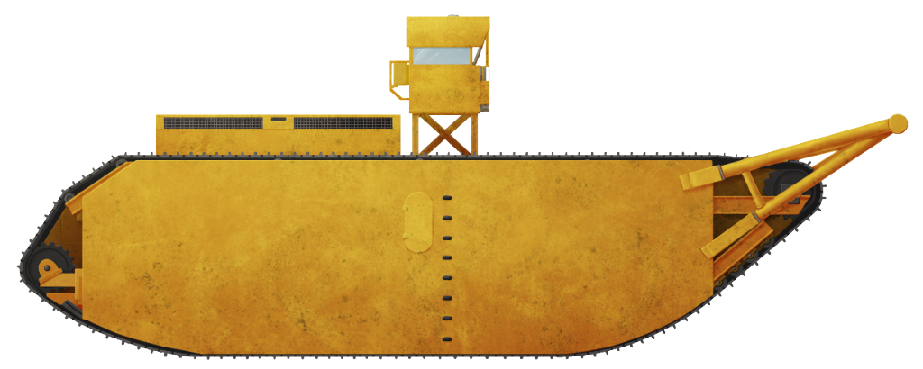
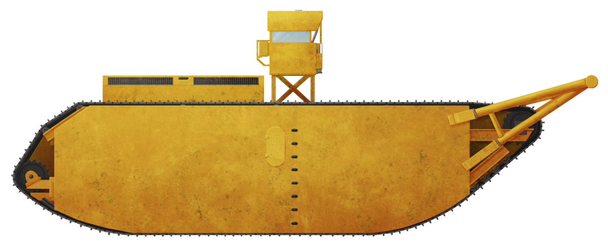
Illustration of the gargantuan Crawler-Crusher – otherwise known as “The Monster”, produced by Andrei ‘Octo10’ Kirushkin, funded by our Patreon Campaign.
16 replies on “Crawler-Crusher, or “The Monster””
To be honest, it looks like they just yanked a Mark V out of Aberdeen (or another museum) and just seriously modified it for construction work. Still, very cool and interesting machine. And good article again guys. Keep up the good work.
Dude, did you see the size of this thing?
I did, it’s massive
Well written in-depth article about this monstrous machine!! Good job!!
In 1973 the Crawler Crusher sat abandoned at what was the location of Florida Prestressed (now a boat manufacturer) between US-1 and the Mosquito Lagoon in Edgewater, FL. My brother worked at prestressed in 73 and talks how large the crawler was and having been used on the canal.
That certainly seems in line with the rumor that it ended up on (or near) one of the intracoastal breakwaters. Could you please possibly ask your brother if he remembers anything else about it?
According to my brother the crawler sat in the back, east, side of Florida Prestressed near the Mosquito Lagoon close to the barge loading dock. The crawler was fully intact but he never saw it move.
Wow. Wonder whatever happened to it. Do you know if your brother might know if it was scrapped or destroyed?
Looks like something dreamed up for an episode of Thunderbirds. That would inevitably end up running amok and smushing a small town.
James Gregg flew a P51 from job to job. He was a brilliant construction pioneer in terms of earth work. Crawlers like this were used to create Rodman and to clear the path of the canal through swamps like no other. Caterpillars joined by huge steel beams leveled trees by the thousands.
Great man and a good man.
Earth Moving and Excavation Company worked on the canal in the Orange Springs are in the mid to late 60s. The same company who did part of the Original Disneyland earth work and owned the land that the City of Coral Springs Florida is built on. James Hunt Jr. dan the earthworks company as his father and his partners developed The Coral Ridge and Galt Ocean Mile area of Fort Lauderdale.
I went to school with Murray Tucker the 3rd. And spent a lot of time at the shop where Charles and Murray 2nd helped build this beat. They are an awesome family.
My Dad (Ted Sowder) was the Service Manager for Ocala Ring Power and took my brothers and neighborhood friends on a field trip to see “The Monster” in about 1966. My Dad was responsible for service repair from Ring Power Corp. The Monster broke down and we have several pictures. I would love to share them, not sure how?
Email? [email protected]
Assuming you don’t have a scanner, laying the pictures flat and taking a picture of them with your phone would be fine. Please do send them to the Tanks Encyclopedia email that stan provided. I would love to see them, and maybe include them in the article if you’d allow.
something like this could be useful to pull large steel cables across a river for the installation of a pre-made bridge